Ambient conditions
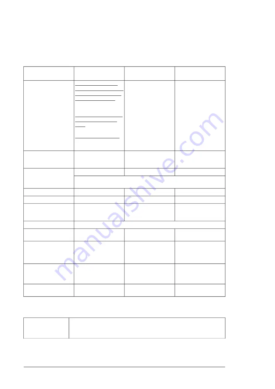
Environmental limits for the drive are given below. The drive is to be used in a heated,
indoor, controlled environment.
Transportation
in the protective package
Storage
in the protective package
Operation
-
-
For TN and TT neutral-
grounded network systems
and IT non-corner-groun-
ded network systems: 0 to
4000 m (13123 ft) above
sea level
For TN, TT and IT corner-
grounded network sys-
tems: 0 to 2000 m (6561 ft)
above sea level
Above 1000 m (3281 ft):
see section
When is derat-
ing necessary
Installation site altitude
-40…+70 °C
-40… 70 °C
-15…+55 °C. No frost al-
lowed. See section
When
is derating necessary
Surrounding air temperat-
ure
Max. 95%
Max. 95%
5…95%
Relative humidity
No condensation allowed. Maximum allowed relative humidity is 60% in the presence
of corrosive gases.
IEC 60721-3-2:1997
IEC 60721-3-1:1997
IEC/EN 60721-3-3:2002
Contamination
Class 2C2
Class 1C2
Class 3C2
Chemical gases
Class 2S2
Class 1S3. (packing must
support this, otherwise
1S2)
Class 3S2. No conductive
dust allowed.
Solid particles
2
Pollution degree
60…106 kPa 0.6 … 1.05
atmospheres
70…106 kPa (0.7 … 1.05
atmospheres)
70…106 kPa (0.7 … 1.05
atmospheres)
Atmospheric pressure
Max. 3.5 mm (0.14 in)
(2…9 Hz), max. 15 m/s
2
(49 ft/s
2
) (9…200 Hz) sinus-
oidal
Max. 1 mm (0.04 in) (5 …
13.2 Hz), max. 7 m/s
2
(23 ft/s
2
) (13.2…100 Hz)
sinusoidal
Max. 0.1 mm (0.004 in)
(10…57 Hz), max. 10 m/s
2
(33 ft/s
2
) (57…150 Hz) si-
nusoidal
Vibration
IEC 60068-2-6:2007,
EN 60068-2-6:2008
With packing max.
100 m/s
2
(330 ft/s
2
), 11 ms
With packing max.
100 m/s
2
(330 ft/s
2
), 11 ms
Not allowed
Shock
IEC 60068-2-27:2008,
EN 60068-2-27:2009
100 mm (4 in) for weight
over 100 kg (220 lb)
100 mm (4 in) for weight
over 100 kg (220 lb)
Not allowed
Free fall
Materials
PC/ABS 2.5 mm, color NCS 1502-Y (RAL 9002 / PMS 420 C)
Drive enclosure
hot-dip zinc coated steel sheet 1.5 to 2.5 mm, thickness of coating 100 micrometers,
color NCS 1502-Y
148 Technical data
Summary of Contents for ACH580-04
Page 1: ... ABB DRIVES FOR HVAC ACH580 04 drive modules Hardware manual ...
Page 2: ......
Page 4: ......
Page 54: ...54 ...
Page 88: ...88 ...
Page 100: ...100 ...
Page 118: ...118 ...
Page 122: ...122 ...
Page 124: ...124 ...
Page 128: ...3 6 5 5 128 Maintenance ...
Page 134: ...134 ...
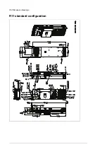
Page 156: ...R10 standard configuration 156 Dimension drawings ...
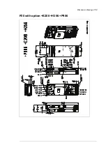
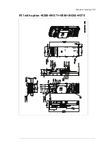
Page 157: ...R10 with E208 0H354 H356 H370 0H371 Dimension drawings 157 ...
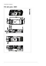
Page 158: ...R10 with option B051 158 Dimension drawings ...
Page 159: ...R10 with option E208 H356 P906 192 Tools R10 3 1 Dimension drawings 159 ...
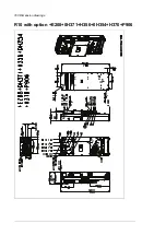
Page 160: ...R10 with option E208 0H371 H356 0H354 H370 P906 Tools 191 R10 2 1 160 Dimension drawings ...
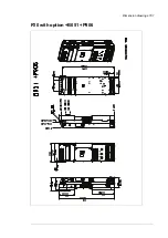
Page 161: ...R10 with option B051 P906 190 Tools R10 1 1 Dimension drawings 161 ...
Page 162: ...R11 standard configuration 162 Dimension drawings ...
Page 163: ...R11 with option E208 0H371 H356 0H354 H370 Dimension drawings 163 ...
Page 164: ...R11 with option B051 164 Dimension drawings ...
Page 165: ...R11 with option E208 H356 P906 Dimension drawings 165 ...
Page 166: ...R11 with option E208 0H371 H356 0H354 H370 P906 166 Dimension drawings ...
Page 167: ...R11 with option B051 P906 Dimension drawings 167 ...
Page 186: ... Declaration of conformity 186 The Safe torque off function ...
Page 206: ...Dimension drawing 206 External control unit option P906 ...
Page 212: ...212 ...
Page 224: ...224 ...
Page 226: ...226 ...
Page 234: ...234 ...


