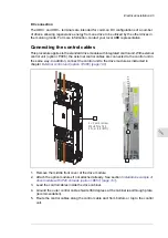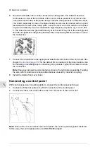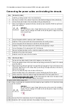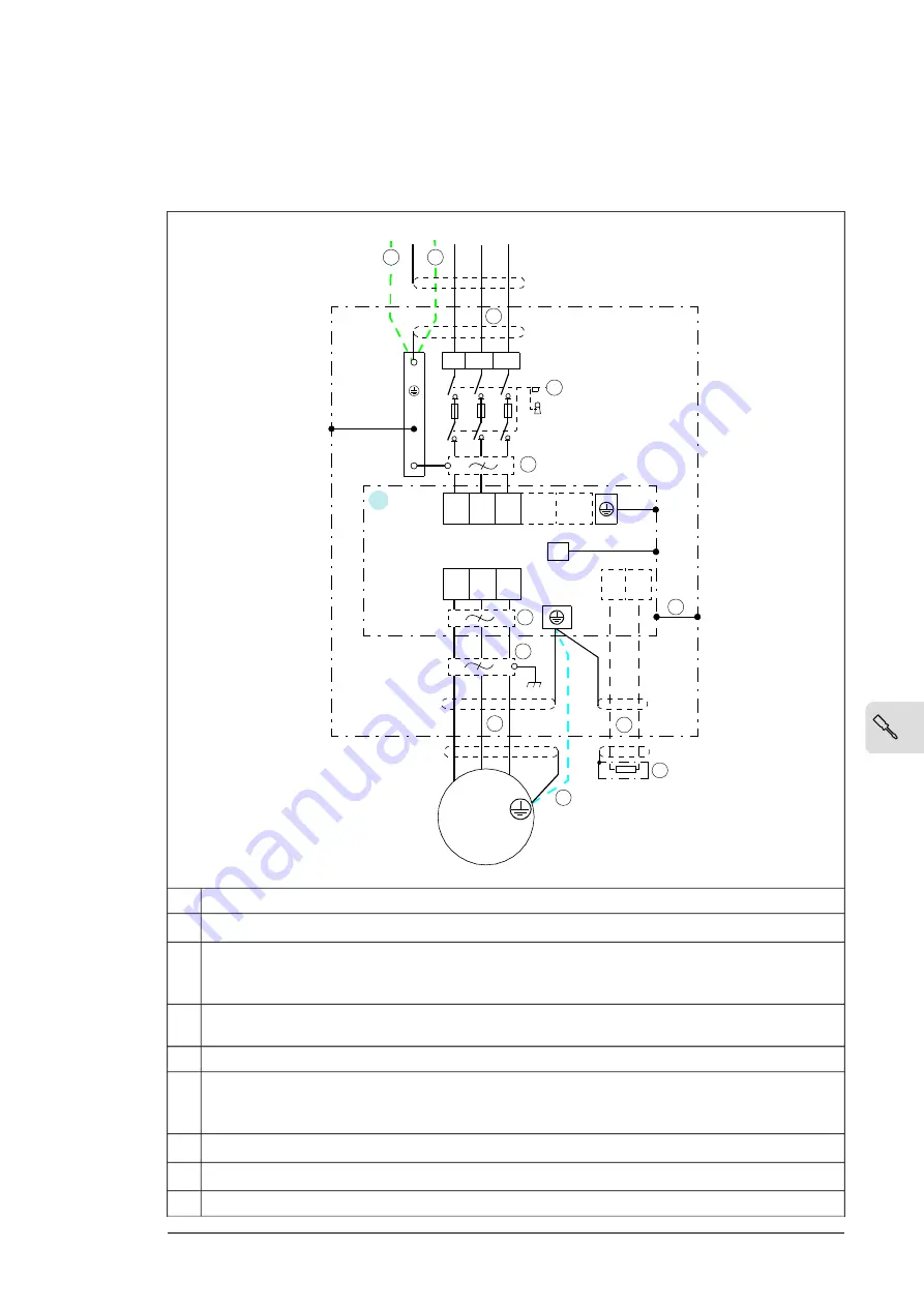
Connecting the power cables
■
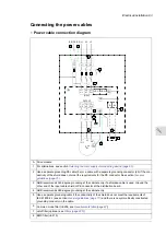
Power cable connection diagram
10
4
INPUT
OUTPUT
U1
V1
W1
M
3
~
(PE) PE (PE)
3
4
5
6
9
L1 L2 L3
L1 L2 L3
1
2a
2b
PE
L1/
U1 V1
L2/ L3/
W1 UDC- UDC+
T1/
U2
T2/
V2
T3/
W2
PE
R- R+
7
8
A
Drive module
A
For alternatives, see section
Selecting the main supply disconnecting device (page 65)
.
1
Use a separate grounding PE cable (2a) or a cable with a separate grounding conductor (2b) if the con-
ductivity of the shield does not meet the requirements for the PE conductor. See section
.
2
ABB recommends 360-degree grounding at the cabinet entry if a shielded cable is used. Ground the
other end of the input cable shield or PE conductor at the distribution board.
3
ABB recommends 360-degree grounding at the cabinet entry.
4
Use a separate grounding cable if the conductivity of the shield does not meet the requirements of
IEC 61800-5-1 (see section
) and there is no symmetrically constructed
grounding conductor in the cable.
5
Common mode filter (+E208, see
)
6
du/dt
filter (optional, see
)
7
EMC filter (+E210)
8
Electrical installation 93
11
Summary of Contents for ACH580-04
Page 1: ... ABB DRIVES FOR HVAC ACH580 04 drive modules Hardware manual ...
Page 2: ......
Page 4: ......
Page 54: ...54 ...
Page 88: ...88 ...
Page 100: ...100 ...
Page 118: ...118 ...
Page 122: ...122 ...
Page 124: ...124 ...
Page 128: ...3 6 5 5 128 Maintenance ...
Page 134: ...134 ...
Page 156: ...R10 standard configuration 156 Dimension drawings ...
Page 157: ...R10 with E208 0H354 H356 H370 0H371 Dimension drawings 157 ...
Page 158: ...R10 with option B051 158 Dimension drawings ...
Page 159: ...R10 with option E208 H356 P906 192 Tools R10 3 1 Dimension drawings 159 ...
Page 160: ...R10 with option E208 0H371 H356 0H354 H370 P906 Tools 191 R10 2 1 160 Dimension drawings ...
Page 161: ...R10 with option B051 P906 190 Tools R10 1 1 Dimension drawings 161 ...
Page 162: ...R11 standard configuration 162 Dimension drawings ...
Page 163: ...R11 with option E208 0H371 H356 0H354 H370 Dimension drawings 163 ...
Page 164: ...R11 with option B051 164 Dimension drawings ...
Page 165: ...R11 with option E208 H356 P906 Dimension drawings 165 ...
Page 166: ...R11 with option E208 0H371 H356 0H354 H370 P906 166 Dimension drawings ...
Page 167: ...R11 with option B051 P906 Dimension drawings 167 ...
Page 186: ... Declaration of conformity 186 The Safe torque off function ...
Page 206: ...Dimension drawing 206 External control unit option P906 ...
Page 212: ...212 ...
Page 224: ...224 ...
Page 226: ...226 ...
Page 234: ...234 ...


