General safety in installation, start-up and maintenance
These instructions are for all personnel who do work on the drive.
WARNING!
Obey these instructions. If you ignore them, injury or death, or damage to
the equipment can occur.
•
Keep the drive in its package until you install it. After unpacking, protect the
drive from dust, debris and moisture.
•
Use the required personal protective equipment: safety shoes with metal toe
cap, safety glasses, protective gloves and long sleeves, etc. Some parts have
sharp edges.
•
Lift a heavy drive with a lifting device. Use the designated lifting points. See
the dimension drawings.
•
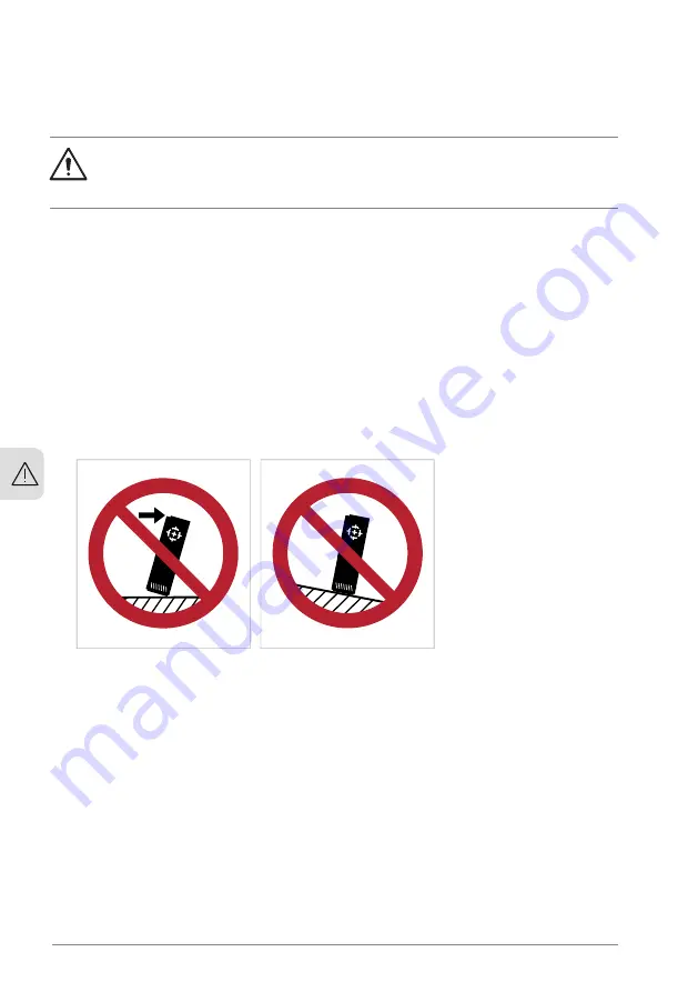
Be careful when handling a tall module. The module overturns easily because
it is heavy and has a high center of gravity. Whenever possible, secure the
module with chains. Do not leave an unsupported module unattended especially
on a sloping floor.
•
Beware of hot surfaces. Some parts, such as heatsinks of power
semiconductors, and brake resistors, remain hot for a while after disconnection
of the electrical supply.
•
Vacuum clean the area around the drive before the start-up to prevent the
drive cooling fan from drawing dust inside the drive.
•
Make sure that debris from drilling, cutting and grinding does not go into the
drive during installation. Electrically conductive debris inside the drive can
cause damage or malfunction.
•
Make sure that there is sufficient cooling. See the technical data.
•
Before you connect voltage to the drive, make sure that all covers are in place.
Do not remove the covers when voltage is connected.
18 Safety instructions
3
Summary of Contents for ACH580-31
Page 1: ... ABB INDUSTRIAL DRIVES ACH580 31 drives Hardware manual ...
Page 2: ......
Page 4: ......
Page 16: ...16 ...
Page 30: ...30 ...
Page 39: ...Operation principle 39 ...
Page 56: ...56 ...
Page 90: ...90 ...
Page 112: ...R3 1 7 N m 112 Electrical installation IEC ...
Page 113: ...R6 1 7 N m Electrical installation IEC 113 ...
Page 114: ...R8 1 7 N m 114 Electrical installation IEC ...
Page 130: ...R3 Max 250 mA 130 Electrical installation North America NEC ...
Page 131: ...R6 Electrical installation North America NEC 131 ...
Page 150: ...150 ...
Page 152: ...152 ...
Page 166: ... Fan arrow must point up 166 Maintenance ...
Page 212: ...212 ...
Page 214: ...R3 IP21 UL Type 1 3AXD50000028643 214 Dimension drawings ...
Page 215: ...R3 Option B056 IP55 UL Type 12 3AXD50000045321 Dimension drawings 215 ...
Page 216: ...R6 IP21 UL Type 1 3AXD50000037446 216 Dimension drawings ...
Page 217: ...R6 Option B056 IP55 UL Type 12 3AXD50000045351 Dimension drawings 217 ...
Page 218: ...R8 IP21 UL Type 1 3AXD50000147052 218 Dimension drawings ...
Page 219: ...R8 Option B056 IP55 UL Type 12 3AXD50000147052 Dimension drawings 219 ...
Page 220: ...220 ...
Page 242: ...242 ...
Page 250: ...250 ...
Page 254: ...254 ...
Page 262: ...262 ...
Page 268: ...268 ...
Page 275: ...CMOD 01 multifunction extension module external 24 V AC DC and digital I O 275 ...
Page 276: ...276 ...
Page 282: ...282 CMOD 02 multifunction extension module external 24 V AC DC and isolated PTC interface ...


