2.
Open the main contactor of the drive with S11.
3.
Switch the motor power supply from the drive to direct-on-line with S40.
4. Wait for 10 seconds to allow the motor magnetization to dissipate.
5. Start the motor with S41.
■
Switching the motor power supply from direct-on-line to drive
1.
Stop the motor with S42.
2.
Switch the motor power supply from direct-on-line to the drive with S40.
3.
Close the main contactor of the drive with switch S11 (-> turn to position ST
for two seconds and leave to position 1).
4. Start the drive and the motor with the drive control panel start key (drive in
the local control mode) or the external start signal (drive in the remote control
mode).
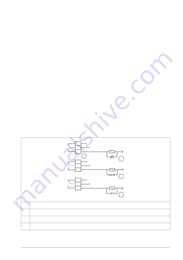
Protecting the contacts of relay outputs
Inductive loads (relays, contactors, motors) cause voltage transients when switched
off.
Install the protective component as close to the inductive load as possible. Do not
install protective components at the relay outputs.
230 V AC
230 V AC
+ 24 V DC
1
2
3
4
Relay output
1
Varistor
2
RC filter
3
Diode
4
Guidelines for planning the electrical installation 87
Summary of Contents for ACH580-31
Page 1: ... ABB INDUSTRIAL DRIVES ACH580 31 drives Hardware manual ...
Page 2: ......
Page 4: ......
Page 16: ...16 ...
Page 30: ...30 ...
Page 39: ...Operation principle 39 ...
Page 56: ...56 ...
Page 90: ...90 ...
Page 112: ...R3 1 7 N m 112 Electrical installation IEC ...
Page 113: ...R6 1 7 N m Electrical installation IEC 113 ...
Page 114: ...R8 1 7 N m 114 Electrical installation IEC ...
Page 130: ...R3 Max 250 mA 130 Electrical installation North America NEC ...
Page 131: ...R6 Electrical installation North America NEC 131 ...
Page 150: ...150 ...
Page 152: ...152 ...
Page 166: ... Fan arrow must point up 166 Maintenance ...
Page 212: ...212 ...
Page 214: ...R3 IP21 UL Type 1 3AXD50000028643 214 Dimension drawings ...
Page 215: ...R3 Option B056 IP55 UL Type 12 3AXD50000045321 Dimension drawings 215 ...
Page 216: ...R6 IP21 UL Type 1 3AXD50000037446 216 Dimension drawings ...
Page 217: ...R6 Option B056 IP55 UL Type 12 3AXD50000045351 Dimension drawings 217 ...
Page 218: ...R8 IP21 UL Type 1 3AXD50000147052 218 Dimension drawings ...
Page 219: ...R8 Option B056 IP55 UL Type 12 3AXD50000147052 Dimension drawings 219 ...
Page 220: ...220 ...
Page 242: ...242 ...
Page 250: ...250 ...
Page 254: ...254 ...
Page 262: ...262 ...
Page 268: ...268 ...
Page 275: ...CMOD 01 multifunction extension module external 24 V AC DC and digital I O 275 ...
Page 276: ...276 ...
Page 282: ...282 CMOD 02 multifunction extension module external 24 V AC DC and isolated PTC interface ...


