ACQ550-U1 User’s Manual
23
Installation
Disconnecting the internal EMC filter
On certain types of systems, you must disconnect the internal EMC filter, otherwise
the system will be connected to ground potential through the EMC filter capacitors,
which might cause danger, or damage the drive.
Note:
When the internal EMC filter is disconnected, the drive is not EMC compatible.
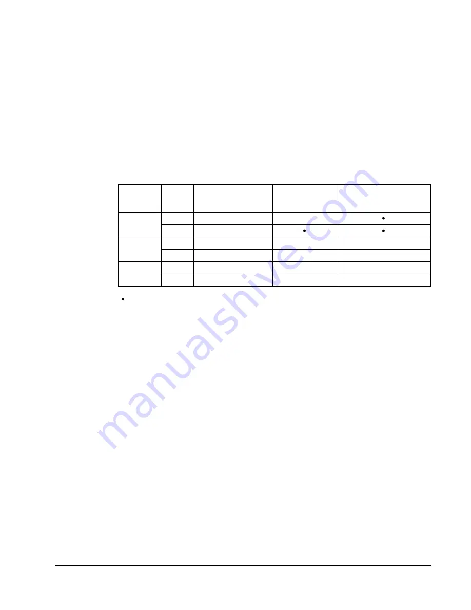
The following table shows the installation rules for the EMC filter screws in order to
connect or disconnect the filter, depending on the system type and the frame size.
For more information on the different system types, see
on page
and
on page
.
The locations of screws EM1 and EM3 are shown in the diagram on page
locations of screws F1 and F2 are shown in the diagram on page
.
Frame
sizes
Screw
Symmetrically
grounded TN systems
(TN-S systems)
Corner grounded
TN systems
IT systems (ungrounded
or high-resistance-
grounded [> 30 ohm])
R1…R3
EM1
x
x
EM3
1
x
R4
EM1
x
x
–
EM3
1
x
–
–
R5…R6
F1
x
x
–
F2
x
x
–
x = Install the screw. (EMC filter will be connected.)
= Replace the screw with the provided polyamide screw. (EMC filter will be disconnected.)
–
= Remove the screw. (EMC filter will be disconnected.)
1
ACQ550-U1 drives are shipped with screw EM3 already removed.
Summary of Contents for ACQ550-U1-011A-6
Page 1: ...ACQ550 User s Manual ACQ550 U1 Drives 1 200 hp ...
Page 4: ......
Page 10: ...10 ACS550 U1 User s Manual Table of contents ...
Page 42: ...42 ACQ550 U1 User s Manual Start up control with I O and ID Run ...
Page 56: ...56 ACQ550 U1 User s Manual Control panel ...
Page 68: ...68 ACQ550 U1 User s Manual Application macros ...
Page 250: ...250 ACQ550 U1 User s Manual Fieldbus adapter ...
Page 266: ...266 ACQ550 U1 User s Manual Maintenance ...
Page 314: ...314 ACQ550 U1 User s Manual Index ...


