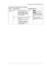
Replacement fans are available from the manufacturer. Do not use other than specified
spare parts.
■
Replacing the cooling fan, frames size R0…R4
WARNING!
Obey the instructions in chapter
. Ignoring the
instructions can cause physical injury or death, or damage to the equipment.
1.
Stop the drive and disconnect it from the power line. Wait for 5 minutes and then make
sure by measuring that there is no voltage. See section
before you start the work.
2.
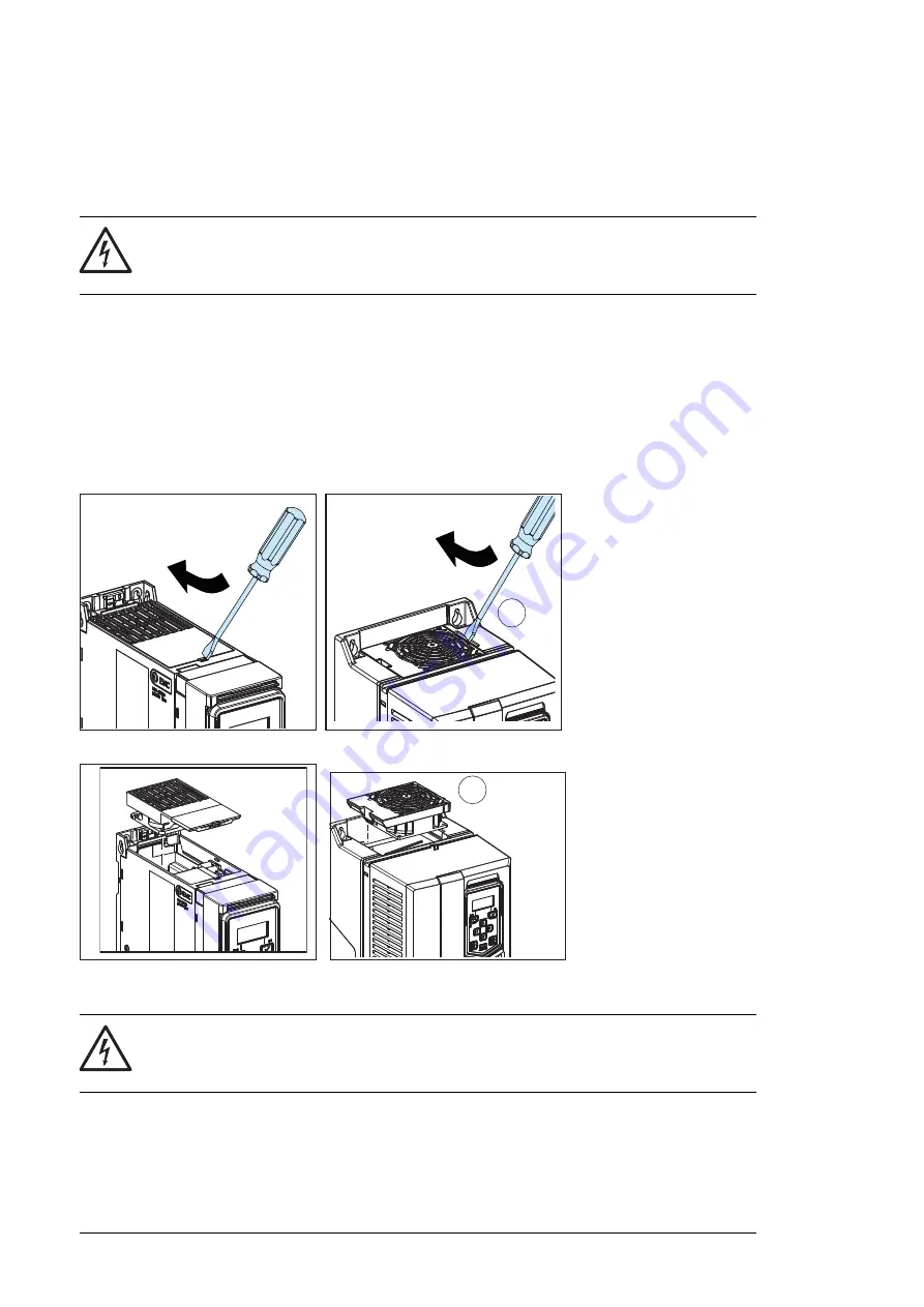
Lever the fan assembly off the drive frames with for example a screwdriver (2a), and
pull out the fan assembly (2b).
3.
Unplug fan power supply wires from the drive.
4.
Install the fan assembly in reverse order.
Maintenance and hardware diagnostics 113
Fans
See section
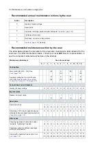
Maintenance intervals
on page
109
for the fan replacement interval in
average operation conditions.
In a speed-controlled fan, the speed of the fan matches the cooling needs. This
increases the life span of the fan.
Replacement fans are available from the manufacturer. Do not use other than
specified spare parts.
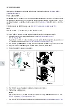
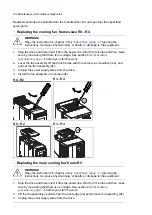
Replacing the cooling fan, frames size R0…R4
WARNING!
Obey the instructions in chapter
11
on page
Safety instructions
.
Ignoring the instructions can cause physical injury or death, or damage to the
equipment.
1. Stop the drive and disconnect it from the power line. Wait for 5 minutes and then
make sure by measuring that there is no voltage. See section
14
on page
Precautions before electrical work
before you start the work.
2. Lever the fan assembly off the drive frames with for example a screwdriver (2a),
and pull out the fan assembly (2b).
3. Unplug fan power supply wires from the drive.
4. Install the fan assembly in reverse order.
2a
05acres
R0...R2
R3...R4
2b
2b
R3...R4
R0...R2
■
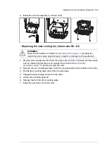
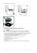
Replacing the main cooling fan, frame R5
WARNING!
Obey the instructions in chapter
. Ignoring the
instructions can cause physical injury or death, or damage to the equipment.
1.
Stop the drive and disconnect it from the power line. Wait for 5 minutes and then make
sure by measuring that there is no voltage. See section
before you start the work.
2.
Lift the fan assembly upwards from the front edge (2a) and remove the assembly (2b).
3.
Unplug fan power supply wires from the drive.
104 Maintenance and hardware diagnostics
Summary of Contents for ACQ80-04 Series
Page 1: ...ABB DRIVES FOR WATER ACQ80 04 drives 0 75 to 160 kW 1 0 to 215 hp Hardware manual...
Page 2: ......
Page 4: ......
Page 18: ...18...
Page 24: ...24...
Page 38: ...38...
Page 50: ...50...
Page 64: ...64...
Page 98: ...98...
Page 110: ...110...
Page 140: ...Frame R3 IP20 140 Dimension drawings...
Page 146: ...146...
Page 162: ...162...
Page 168: ......


