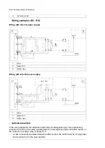
Activation switch
K
■
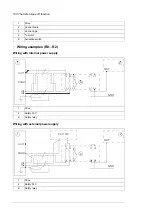
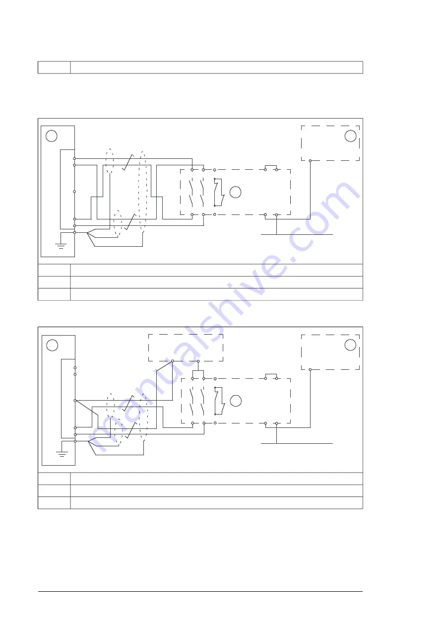
Wiring examples (R3…R8)
Wiring with internal power supply
24
14
23
13
Y1
A2
Y2
A1
31
32
OUT
GND
K
1
2
OUT1
34
OUT2
35
SGND
36
IN1
37
IN2
38
STO
Drive
1
Safety PLC
2
Safety relay
K
Wiring with external power supply
24
14
23
13
Y1
A2
Y2
A1
31
32
OUT
GND
K
-
+
2
24 V DC
1
OUT1
34
OUT2
35
SGND
36
IN1
37
IN2
38
STO
Drive
1
Safety PLC
2
Safety relay
K
■
Activation switch
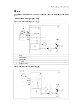
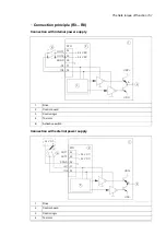
In the wiring diagrams, the activation switch has the designation [K]. This represents a
component such as a manually operated switch, an emergency stop push button switch, or
the contacts of a safety relay or safety PLC.
•
In case a manually operated activation switch is used, the switch must be of a type that
can be locked out to the open position.
152 The Safe torque off function
Summary of Contents for ACQ80-04 Series
Page 1: ...ABB DRIVES FOR WATER ACQ80 04 drives 0 75 to 160 kW 1 0 to 215 hp Hardware manual...
Page 2: ......
Page 4: ......
Page 18: ...18...
Page 24: ...24...
Page 38: ...38...
Page 50: ...50...
Page 64: ...64...
Page 98: ...98...
Page 110: ...110...
Page 140: ...Frame R3 IP20 140 Dimension drawings...
Page 146: ...146...
Page 162: ...162...
Page 168: ......


