60
ACS 300 User’s Manual
Chapter 7 - Drive Parameters
apply the analogue input signal that represents minimum
frequency in your system. Press and hold the
key for three
seconds. The setting is accepted when * blinks once on the
Control Panel display. To set the maximum reference signal level,
scroll to SET MAX and repeat the procedure as for SET MIN.
Note! The drive will stop, a fault message “LOW AI-SIGNAL”
appears and the fault LED lights if parameter AI-FAULT (refer to
page 67) has been enabled and the reference drops below the
selected minimum limit.
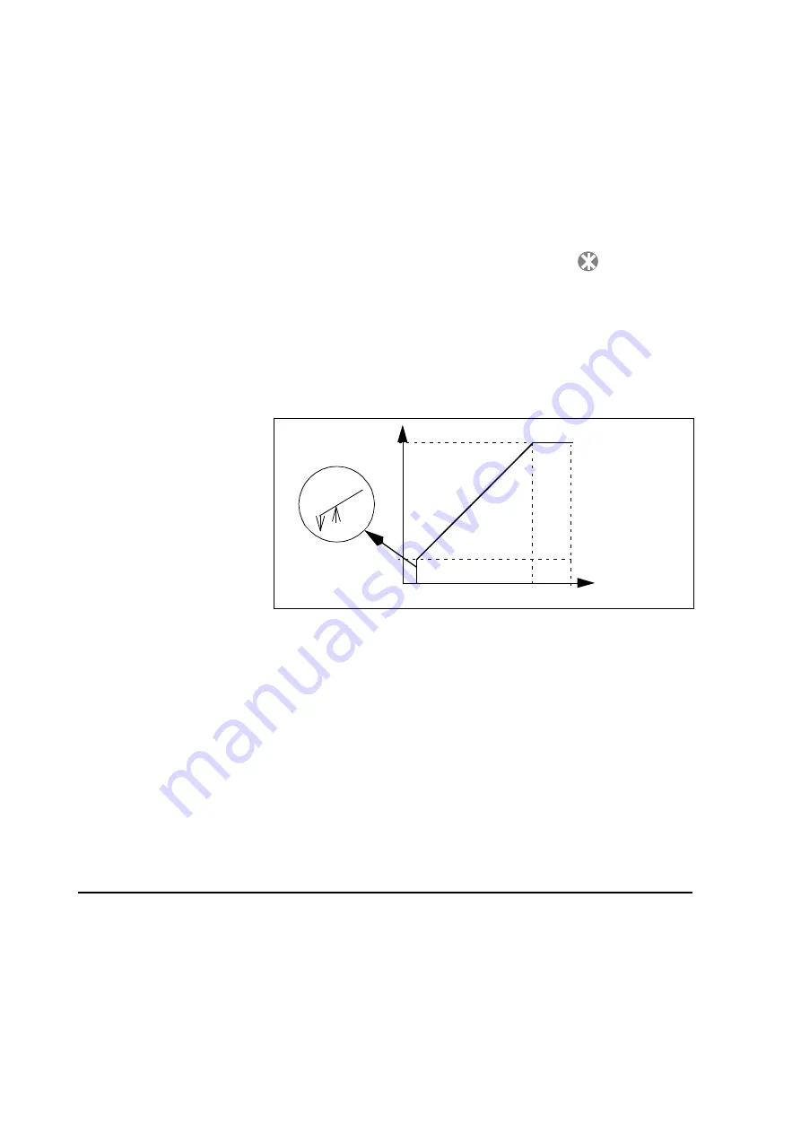
Figure 7-3 Customised minimum and maximum limits for the
reference input.
A. OUT
This parameter selects which signal is connected to analogue
output.
NONE– Analogue output is 0 mA.
OUT FREQ– Output frequency (0 to the selected maximum
frequency)
REF FREQ– Reference frequency (0 to the selected maximum
frequency)
MOTOR CUR– Motor current (0 to 1.5 x I
N
, see Table 1-1 and
Table 1-2)
Hysteresis
2 %
Output frequency
Analogue Input
MAX FREQ
MIN FREQ
0
CUSTOM
MIN
CUSTOM
MAX
10 v/ 20mA
(100%)
Summary of Contents for ACS 300
Page 14: ...xiv ACS 300 User s Manual Table of Contents ...
Page 24: ...10 ACS 300 User s Manual Chapter 1 Overview of This Manual ...
Page 28: ...14 ACS 300 User s Manual Chapter 2 Mechanical Installation ...
Page 50: ...36 ACS 300 User s Manual Chapter 4 Control Connections ...
Page 60: ...46 ACS 300 User s Manual Chapter 6 Control and Parameter Logic ...


