ACS 400 User’s Manual
129
Standard Serial Communication
Overview
The ACS 400 can be connected to an external control system using the standard Modbus fieldbus
connection.
The ACS 400 can receive all of its control information either from the Modbus fieldbus, or the
control can be distributed between the fieldbus and other available control locations, e.g. digital/
analog inputs and the drive control panel.
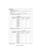
The ACS 400 has two serial communication channels (or ports), Channel 0 and Channel 1.
Channel 1 is the standard Modbus fieldbus connection. Communication settings of Channel 1 can
be configured by the user. To control the ACS 400 via Modbus, the ACS 400 must be programmed
to accept control commands and/or frequency references from Channel 1. Channel 0 is reserved
for drive control panels ACS-PAN and ACS100-PAN, and for the DriveWindow PC tool.
Optional serial communication features
The ACS 400 can also be connected to a number of other fieldbuses using special fieldbus adapter
modules. These adapters are connected using an optical DDCS link (DDCS=Distributed Drives
Control System). For more information on these options, contact your supplier.
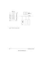
Figure 55 Standard serial communication features of ACS 400.
Channel 1
Connector X3
Modbus fieldbus (RS485)
Channel 0
ACS100-PAN
ACS-PAN
DriveWindow
ENTER
MENU
LOC RE M
mAVs
SET
OUTPUTPAR MENU FWDREV
o
Crpm
%
REM
LOC
kHz
FAULT
LOC
REM
ACS 400
Connector for optional DDCS
communication module
http://nicontrols.com
Summary of Contents for ACS 400
Page 3: ...http nicontrols com ...
Page 5: ...http nicontrols com ...
Page 7: ...iv ACS 400 User s Manual http nicontrols com ...
Page 45: ...34 ACS 400 User s Manual http nicontrols com ...
Page 52: ...ACS 400 User s Manual 41 Motor Will Not Run http nicontrols com ...
Page 53: ...42 ACS 400 User s Manual Motor Stalls during Acceleration http nicontrols com ...
Page 54: ...ACS 400 User s Manual 43 Overvoltage Fault Indication http nicontrols com ...
Page 55: ...44 ACS 400 User s Manual Overcurrent Fault Indication http nicontrols com ...
Page 56: ...ACS 400 User s Manual 45 Overload Fault Indication http nicontrols com ...
Page 57: ...46 ACS 400 User s Manual Undervoltage Fault Indication http nicontrols com ...
Page 58: ...ACS 400 User s Manual 47 External Fault Indication http nicontrols com ...
Page 59: ...48 ACS 400 User s Manual No Operator Display http nicontrols com ...
Page 75: ...64 ACS 400 User s Manual http nicontrols com ...
Page 161: ...150 ACS 400 User s Manual http nicontrols com ...
Page 167: ...156 ACS 400 User s Manual http nicontrols com ...
Page 177: ...166 ACS 400 User s Manual http nicontrols com ...
Page 179: ...168 ACS 400 User s Manual ACS 400 NEMA Type 1 Enclosure R2 Frame Size http nicontrols com ...
Page 180: ...ACS 400 User s Manual 169 ACS 400 NEMA Type 1 Enclosure R3 Frame Size http nicontrols com ...
Page 181: ...170 ACS 400 User s Manual ACS 400 NEMA Type 1 Enclosure R4 Frame Size http nicontrols com ...
Page 182: ...ACS 400 User s Manual 171 ACS 400 NEMA Type 12 4 Enclosure R1 Frame Size http nicontrols com ...
Page 183: ...172 ACS 400 User s Manual ACS 400 NEMA 12 4 Enclosure R2 Frame Size http nicontrols com ...
Page 184: ...ACS 400 User s Manual 173 ACS 400 NEMA Type 12 4 R3 Frame Size http nicontrols com ...
Page 185: ...174 ACS 400 User s Manual ACS 400 NEMA Type 12 4 R4 Frame Size http nicontrols com ...
Page 186: ...http nicontrols com ...

