162
ACS 400 User’s Manual
Cabling Instructions
Keep individual unscreened wires between the cable clamps and the screw terminals as short as
possible. Route control cables away from power cables.
Mains Cable
A four conductor cable (three phase with protective earth) is recommended for the mains cabling.
Shielding is not necessary. Dimension the cables and fuses in accordance with the input current.
Always pay attention to local legislation when sizing the cables and fuses.
The mains input connectors are at the bottom of the converter unit. Mains cable routing must be
done so that the distance from the sides of the converter is at least 20 cm to avoid excessive
radiation to the mains cable. In the case of shielded cable, twist the cable screen wires together into
a bundle not longer than five times its width and connect to the PE terminal of the converter. (Or PE
terminal of input filter, if present.)
Motor Cable
The motor cable must be a symmetrical three conductor cable with a concentric PE conductor or a
four conductor cable with a concentric shield, however, a symmetrical constructed PE conductor is
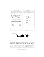
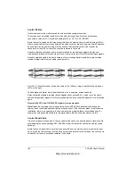
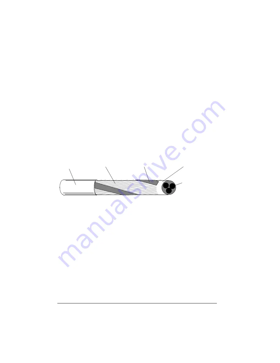
always recommended. Minimum requirement for the motor cable screen is presented in Figure 66.
Figure 66 Minimum requirement for motor cable screen (e.g. MCMK, NK Cables).
Insulation jacket
Copper wire screen
Helix of copper tape
Cable core
Inner insulation
http://nicontrols.com
Summary of Contents for ACS 400
Page 3: ...http nicontrols com ...
Page 5: ...http nicontrols com ...
Page 7: ...iv ACS 400 User s Manual http nicontrols com ...
Page 45: ...34 ACS 400 User s Manual http nicontrols com ...
Page 52: ...ACS 400 User s Manual 41 Motor Will Not Run http nicontrols com ...
Page 53: ...42 ACS 400 User s Manual Motor Stalls during Acceleration http nicontrols com ...
Page 54: ...ACS 400 User s Manual 43 Overvoltage Fault Indication http nicontrols com ...
Page 55: ...44 ACS 400 User s Manual Overcurrent Fault Indication http nicontrols com ...
Page 56: ...ACS 400 User s Manual 45 Overload Fault Indication http nicontrols com ...
Page 57: ...46 ACS 400 User s Manual Undervoltage Fault Indication http nicontrols com ...
Page 58: ...ACS 400 User s Manual 47 External Fault Indication http nicontrols com ...
Page 59: ...48 ACS 400 User s Manual No Operator Display http nicontrols com ...
Page 75: ...64 ACS 400 User s Manual http nicontrols com ...
Page 161: ...150 ACS 400 User s Manual http nicontrols com ...
Page 167: ...156 ACS 400 User s Manual http nicontrols com ...
Page 177: ...166 ACS 400 User s Manual http nicontrols com ...
Page 179: ...168 ACS 400 User s Manual ACS 400 NEMA Type 1 Enclosure R2 Frame Size http nicontrols com ...
Page 180: ...ACS 400 User s Manual 169 ACS 400 NEMA Type 1 Enclosure R3 Frame Size http nicontrols com ...
Page 181: ...170 ACS 400 User s Manual ACS 400 NEMA Type 1 Enclosure R4 Frame Size http nicontrols com ...
Page 182: ...ACS 400 User s Manual 171 ACS 400 NEMA Type 12 4 Enclosure R1 Frame Size http nicontrols com ...
Page 183: ...172 ACS 400 User s Manual ACS 400 NEMA 12 4 Enclosure R2 Frame Size http nicontrols com ...
Page 184: ...ACS 400 User s Manual 173 ACS 400 NEMA Type 12 4 R3 Frame Size http nicontrols com ...
Page 185: ...174 ACS 400 User s Manual ACS 400 NEMA Type 12 4 R4 Frame Size http nicontrols com ...
Page 186: ...http nicontrols com ...


