ACS 400 User’s Manual
163
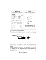
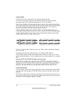
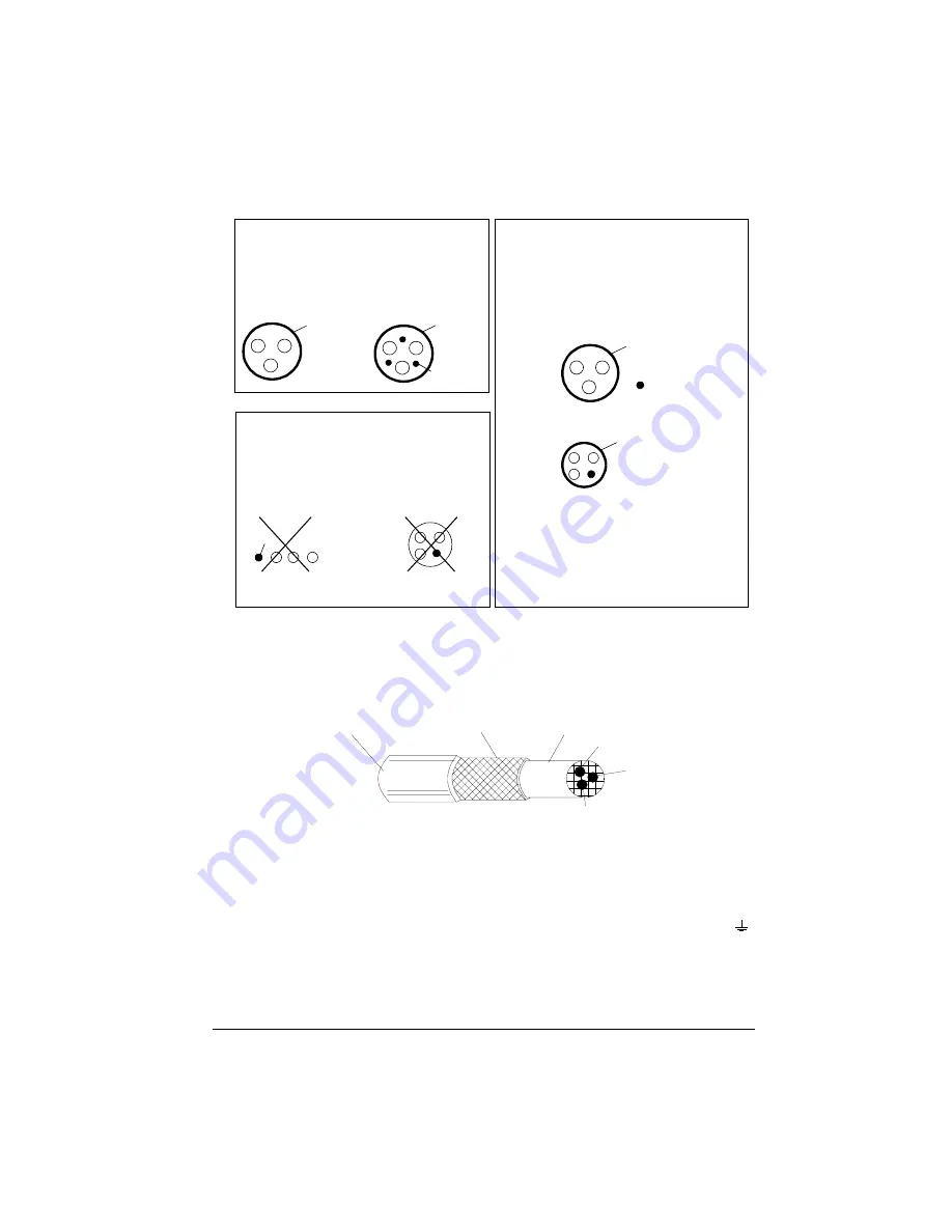
Figure 67 Cable recommendations and restrictions.
The general rule for cable screen effectiveness is: the better and tighter the screen of the cable, the
lower the radiated emission level. Example of an effective construction is presented in Figure 68.
Figure 68 Effective motor cable screen (e.g. Ölflex-Servo-FD 780 CP, Lappkabel or MCCMK, NK
Cables).
Clamp the cable shield into the gland plate at the converter end and twist the cable screen wires
together into a bundle not longer than five times its width and connect it to the terminal marked
(at the bottom right-hand corner of the converter), if you are using cable without a separate PE
conductor.
At the motor end the motor cable screen must be earthed 360 degrees with an EMC cable gland
(e.g. ZEMREX SCG Screened cable glands) or the screen wires must be twisted together into a
bundle not longer than five times its width and connected to the PE terminal of the motor.
Symmetrical shielded cable: three phase
conductors and a concentric or otherwise
symmetrically constructed PE conductor,
and a shield
Recommended
PE
conductor
and shield
Shield
Shield
A separate PE conductor is required if the
conductivity of the cable shield is < 50 %
of the conductivity of the phase conductor.
Not allowed for motor cables.
Shield
PE
PE
PE
Allowed for motor cables with phase
conductor cross section up to 10 mm
2
.
A four -conductor system: three phase
conductors and a protective conductor.
Allowed
Insulation jacket
Braided metallic screen
Inner insulator
L1
L2
L3
http://nicontrols.com
Summary of Contents for ACS 400
Page 3: ...http nicontrols com ...
Page 5: ...http nicontrols com ...
Page 7: ...iv ACS 400 User s Manual http nicontrols com ...
Page 45: ...34 ACS 400 User s Manual http nicontrols com ...
Page 52: ...ACS 400 User s Manual 41 Motor Will Not Run http nicontrols com ...
Page 53: ...42 ACS 400 User s Manual Motor Stalls during Acceleration http nicontrols com ...
Page 54: ...ACS 400 User s Manual 43 Overvoltage Fault Indication http nicontrols com ...
Page 55: ...44 ACS 400 User s Manual Overcurrent Fault Indication http nicontrols com ...
Page 56: ...ACS 400 User s Manual 45 Overload Fault Indication http nicontrols com ...
Page 57: ...46 ACS 400 User s Manual Undervoltage Fault Indication http nicontrols com ...
Page 58: ...ACS 400 User s Manual 47 External Fault Indication http nicontrols com ...
Page 59: ...48 ACS 400 User s Manual No Operator Display http nicontrols com ...
Page 75: ...64 ACS 400 User s Manual http nicontrols com ...
Page 161: ...150 ACS 400 User s Manual http nicontrols com ...
Page 167: ...156 ACS 400 User s Manual http nicontrols com ...
Page 177: ...166 ACS 400 User s Manual http nicontrols com ...
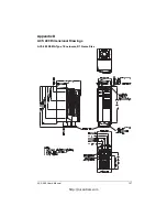
Page 179: ...168 ACS 400 User s Manual ACS 400 NEMA Type 1 Enclosure R2 Frame Size http nicontrols com ...
Page 180: ...ACS 400 User s Manual 169 ACS 400 NEMA Type 1 Enclosure R3 Frame Size http nicontrols com ...
Page 181: ...170 ACS 400 User s Manual ACS 400 NEMA Type 1 Enclosure R4 Frame Size http nicontrols com ...
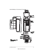
Page 182: ...ACS 400 User s Manual 171 ACS 400 NEMA Type 12 4 Enclosure R1 Frame Size http nicontrols com ...
Page 183: ...172 ACS 400 User s Manual ACS 400 NEMA 12 4 Enclosure R2 Frame Size http nicontrols com ...
Page 184: ...ACS 400 User s Manual 173 ACS 400 NEMA Type 12 4 R3 Frame Size http nicontrols com ...
Page 185: ...174 ACS 400 User s Manual ACS 400 NEMA Type 12 4 R4 Frame Size http nicontrols com ...
Page 186: ...http nicontrols com ...


