134
ACS 400 User’s Manual
Control Locations
The ACS 400 drive can receive control information from multiple sources, including digital I/O,
analog I/O, keypad, and Modbus fieldbus.
To control the ACS 400 via the serial communication channel 1 (Modbus fieldbus), it must be
pprogrammed to accept control commands and/or frequency references from this channel. In
addition, ACS 400 must be in remote control.
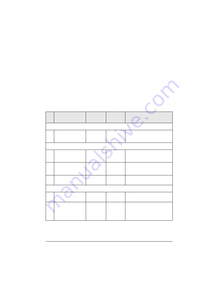
The necessary parameters and their usage are listed in Table 15. Note especially, that before any
control commands can be given through serial communication channel 1, parameter 5006
COMM
COMMANDS
value must be set to
STD
MODBUS
.
Further information on all the parameters and their alternative settings is given in “ACS 400
Complete Parameter List” on page 65.
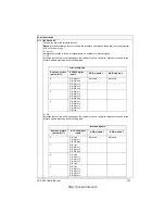
Table 15 Parameters for control command source selection.
Code Parameter Name
Alternative
Settings
Setting for
Standard
Modbus
Function/Information
Group 50
COMMUNICATION
5006
COMM
COMMAND
0 =
NOT
SEL
1 =
STD
MODBUS
,
2 =
DDCS
1 (
STD
MODBUS
) Defines the serial communication channel
for the controlling commands (start, stop,
direction and reference). Must be set to 1
(
STD
MODBUS
).
Group 10
COMMAND INPUTS
1001
EXT
1
COMMANDS
0 =
NOT
SEL
1 =
DI
1
...
10 =
COMM
10 (
COMM
)
Enables the Control Word (except bit 11)
when EXT1 is selected as control
location.
1002
EXT
2
COMMANDS
0 =
NOT
SEL
1 =
DI
1
...
10 =
COMM
10 (
COMM
)
Enables the Control Word (except bit 11)
when EXT2 is selected as control
location.
1003
DIRECTION
1 =
FORWARD
2 =
REVERSE
3 =
REQUEST
3 (
REQUEST
)
Enables rotation direction control as
defined by parameters 1001 and 1002.
Group 11
REFERENCE SELECT
1102
EXT
1/
EXT
2
SEL
1 =
DI
1
...
8 =
COMM
8 (
COMM
)
Enables external control location EXT1/
EXT2 selection by Control Word bit 11.
1103
EXT
REF
1
SELECT
0 =
KEYPAD
1 =
AI
1
...
8 =
COMM
9 =
COMM
+
AI
1
10 =
COMM
*
AI
1
8 (
COMM
),
9 (
COMM
+
AI
1)
or
10 (
COMM
*
AI
1)
Fieldbus reference 1 is used when EXT1
is selected as control location. See
section References below for information
on the alternative settings.
http://nicontrols.com
Summary of Contents for ACS 400
Page 3: ...http nicontrols com ...
Page 5: ...http nicontrols com ...
Page 7: ...iv ACS 400 User s Manual http nicontrols com ...
Page 45: ...34 ACS 400 User s Manual http nicontrols com ...
Page 52: ...ACS 400 User s Manual 41 Motor Will Not Run http nicontrols com ...
Page 53: ...42 ACS 400 User s Manual Motor Stalls during Acceleration http nicontrols com ...
Page 54: ...ACS 400 User s Manual 43 Overvoltage Fault Indication http nicontrols com ...
Page 55: ...44 ACS 400 User s Manual Overcurrent Fault Indication http nicontrols com ...
Page 56: ...ACS 400 User s Manual 45 Overload Fault Indication http nicontrols com ...
Page 57: ...46 ACS 400 User s Manual Undervoltage Fault Indication http nicontrols com ...
Page 58: ...ACS 400 User s Manual 47 External Fault Indication http nicontrols com ...
Page 59: ...48 ACS 400 User s Manual No Operator Display http nicontrols com ...
Page 75: ...64 ACS 400 User s Manual http nicontrols com ...
Page 161: ...150 ACS 400 User s Manual http nicontrols com ...
Page 167: ...156 ACS 400 User s Manual http nicontrols com ...
Page 177: ...166 ACS 400 User s Manual http nicontrols com ...
Page 179: ...168 ACS 400 User s Manual ACS 400 NEMA Type 1 Enclosure R2 Frame Size http nicontrols com ...
Page 180: ...ACS 400 User s Manual 169 ACS 400 NEMA Type 1 Enclosure R3 Frame Size http nicontrols com ...
Page 181: ...170 ACS 400 User s Manual ACS 400 NEMA Type 1 Enclosure R4 Frame Size http nicontrols com ...
Page 182: ...ACS 400 User s Manual 171 ACS 400 NEMA Type 12 4 Enclosure R1 Frame Size http nicontrols com ...
Page 183: ...172 ACS 400 User s Manual ACS 400 NEMA 12 4 Enclosure R2 Frame Size http nicontrols com ...
Page 184: ...ACS 400 User s Manual 173 ACS 400 NEMA Type 12 4 R3 Frame Size http nicontrols com ...
Page 185: ...174 ACS 400 User s Manual ACS 400 NEMA Type 12 4 R4 Frame Size http nicontrols com ...
Page 186: ...http nicontrols com ...

