138
ACS 400 User’s Manual
Communication
This chapter describes the Modbus communication on ACS 400 drives.
Introduction to Modbus
Modbus is a serial, asynchronous protocol. The Modbus protocol does not specify the physical
interface. Typical physical interface is RS485.
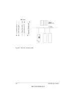
Modbus is designed for integration with Modicon PLCs or other automation devices, and the
services closely correspond to the PLC architecture. The ACS 400 drive ‘looks like’ a Modicon PLC
on the network.
If detailed information regarding the Modicon Modbus protocol is required, contact your ABB
supplier for a copy of the Modbus Protocol Guide.
Register Read and Write
The ACS 400 has all drive parameter, control and status information mapped into a 4xxxx register
area. This holding register area can be read from an external device, and an external device can
modify the register values by writing to them.
There are no setup parameters for mapping the data to the 4xxxx register. The mapping is
predefined and corresponds directly to the ACS 400 parameter grouping.
All parameters are available for both reading and writing. The parameter writes are verified for
correct value, and for valid register addresses. Some parameters never allow writes (including
Group 1 actual values), some allow only zero write (including Group 1 fault memories), some
parameters allow write only when the drive is stopped (including Group 99 setup variables), and
some can be modified at any time (including e.g. Group 22 acceleration and deceleration ramp
times).
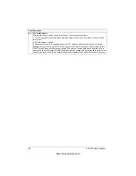
Note! Parameter writes through Channel 1 (Standard Modbus) are always volatile, i.e. modified
values are not automatically stored to permanent memory. Parameter 1607
PARAM
.
SAVE
can be
used to save all altered values.
http://nicontrols.com
Summary of Contents for ACS 400
Page 3: ...http nicontrols com ...
Page 5: ...http nicontrols com ...
Page 7: ...iv ACS 400 User s Manual http nicontrols com ...
Page 45: ...34 ACS 400 User s Manual http nicontrols com ...
Page 52: ...ACS 400 User s Manual 41 Motor Will Not Run http nicontrols com ...
Page 53: ...42 ACS 400 User s Manual Motor Stalls during Acceleration http nicontrols com ...
Page 54: ...ACS 400 User s Manual 43 Overvoltage Fault Indication http nicontrols com ...
Page 55: ...44 ACS 400 User s Manual Overcurrent Fault Indication http nicontrols com ...
Page 56: ...ACS 400 User s Manual 45 Overload Fault Indication http nicontrols com ...
Page 57: ...46 ACS 400 User s Manual Undervoltage Fault Indication http nicontrols com ...
Page 58: ...ACS 400 User s Manual 47 External Fault Indication http nicontrols com ...
Page 59: ...48 ACS 400 User s Manual No Operator Display http nicontrols com ...
Page 75: ...64 ACS 400 User s Manual http nicontrols com ...
Page 161: ...150 ACS 400 User s Manual http nicontrols com ...
Page 167: ...156 ACS 400 User s Manual http nicontrols com ...
Page 177: ...166 ACS 400 User s Manual http nicontrols com ...
Page 179: ...168 ACS 400 User s Manual ACS 400 NEMA Type 1 Enclosure R2 Frame Size http nicontrols com ...
Page 180: ...ACS 400 User s Manual 169 ACS 400 NEMA Type 1 Enclosure R3 Frame Size http nicontrols com ...
Page 181: ...170 ACS 400 User s Manual ACS 400 NEMA Type 1 Enclosure R4 Frame Size http nicontrols com ...
Page 182: ...ACS 400 User s Manual 171 ACS 400 NEMA Type 12 4 Enclosure R1 Frame Size http nicontrols com ...
Page 183: ...172 ACS 400 User s Manual ACS 400 NEMA 12 4 Enclosure R2 Frame Size http nicontrols com ...
Page 184: ...ACS 400 User s Manual 173 ACS 400 NEMA Type 12 4 R3 Frame Size http nicontrols com ...
Page 185: ...174 ACS 400 User s Manual ACS 400 NEMA Type 12 4 R4 Frame Size http nicontrols com ...
Page 186: ...http nicontrols com ...


