Chapter 4 – Parameters
ACS 600 Master/Follower Application Macro
4-11
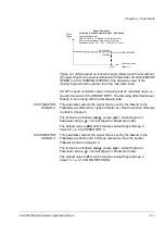
Figure 4-3 Actual speed at constant speed reference with and without
drooping. Maximum speed is defined with Parameter 20.02 MAXIMUM
SPEED (or 20.01 MINIMUM SPEED if the absolute value of the
minimum speed limit is greater than the maximum limit).
At 100% speed controller output, drooping is at its maximum level, i.e.
equal to the value of the DROOP RATE. The drooping effect decreases
linearly to zero along with the decreasing load.
60.07 MASTER
SIGNAL 2
This parameter selects the signal that is sent by the Master to the
Follower(s) as
Reference 1 (speed reference). See the section Follower
Control in Chapter 3.
The format is as follows: (x)xyy, where (x)x = Actual Signal or
Parameter Group, yy = Actual Signal or Parameter Index.
The default value is 202, which denotes Actual Signal Group 2,
Index 02, i.e. 2.02 SPEED REF 3.
60.08 MASTER
SIGNAL 3
This parameter selects the signal that is sent by the Master to the
Follower(s) as
Reference 2 (torque reference). See the section
Follower Control in Chapter 3.
The format is as follows: (x)xyy, where (x)x = Actual Signal or
Parameter Group, yy = Actual Signal or Parameter Index.
The default value is 213, which denotes Actual Signal Group 2,
Index 13, i.e. 2.13 TORQ REF USED.
Motor
Speed
%
Drooping
No Drooping
Speed Controller
100%
} Par. 60.06 DROOP RATE
Output /%
Speed Decrease =
Drooping · Speed Controller Output · Max. Speed
Calculation Example:
DROOP RATE is 1%, Speed Controller output is
50%, maximum speed of the drive is 1500 rpm.
Speed decrease = 0.01 · 0.50 · 1500 rpm = 7.5 rpm
Summary of Contents for ACS 600
Page 2: ......
Page 4: ......
Page 6: ...iv ACS 600 Master Follower Application Macro...
Page 30: ...Chapter 4 Parameters 4 12 ACS 600 Master Follower Application Macro...
Page 38: ...Appendix B Parameter Settings B 4 ACS 600 Master Follower Application Macro...
Page 41: ......


