10 PREVENTIVE AND CORRECTIVE MAINTENANCE
3BHS212794 E01 REV M
ACS6000
USER MANUAL
228/278
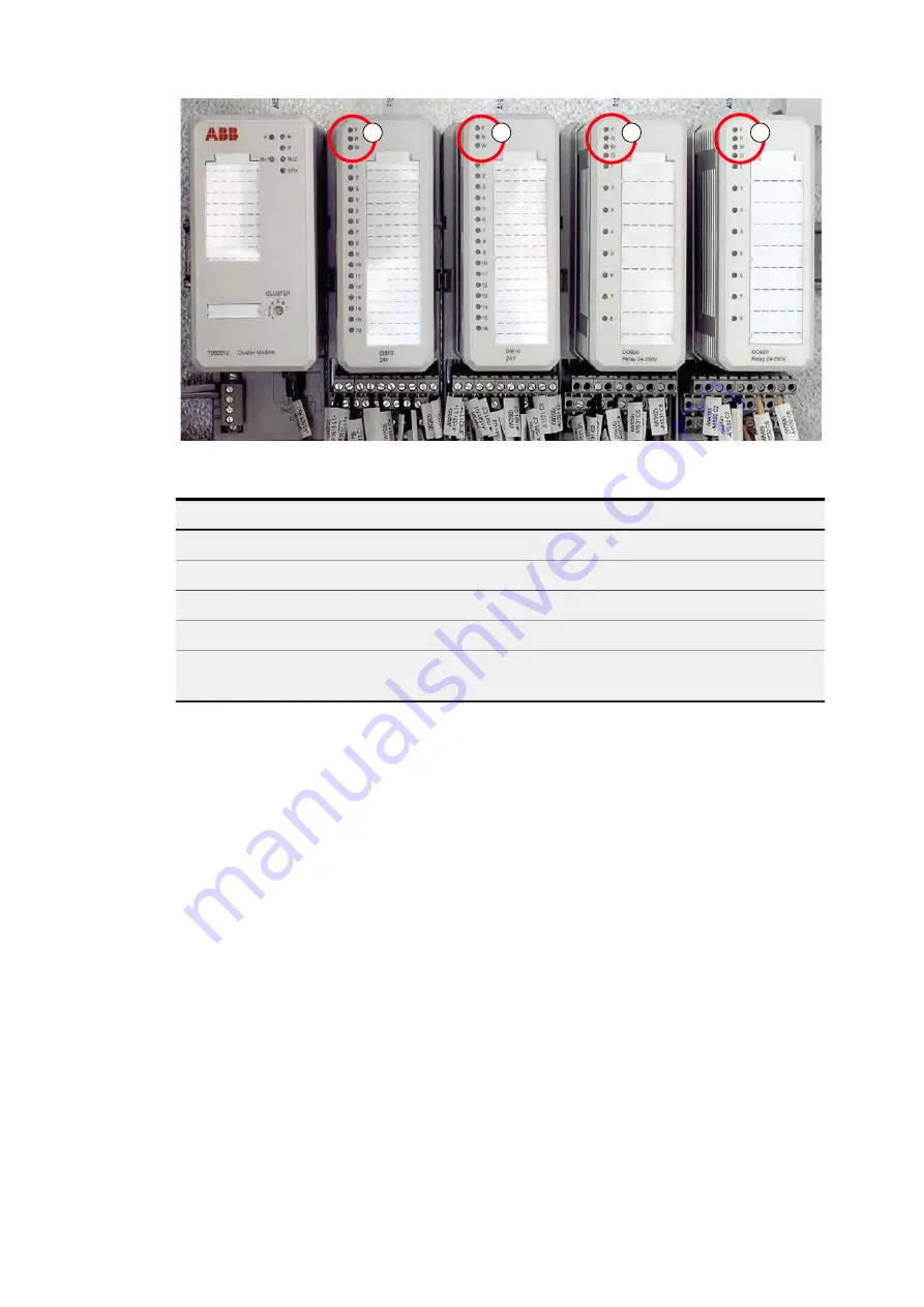
Figure 10-5 Example of S800 I/O station
Note:
For more information, see the following manuals:
• S800 I/O - General information and installation, user’s guide
• S800 I/O - Modules and termination unit, user’s guide
10.3.3.4 Serial communication interfaces
To identify the serial communication interface in the drive, see “Appendix
D – Wiring diagrams”. For more information on the device, select the
appropriate manual:
• "AF 100 fieldbus - NAFA-01 installation and start-up guide"
• "Modbus TCP - NETA-21 remote monitoring tool user manual"
• "Modbus RTU - NMBA-01 installation and startup guide"
• "Profibus - NPBA-12 installation and startup guide" (3BFE64341588)
LED
Color
Indication
F
Red
Indicates failure
R
Green
Device is operating normally
W
Yellow
External fault or minor fault in the module
O
Yellow
Indicates an active signal
OSP
Yellow
Indicates an active signal
(Output Set as Predetermined)
1
1
1
1


