Chapter 9 - Changing Thyristors in EXU
ABB
9-6 (8)
3BHS202077 ZAB E01 Rev. C
ACS 6000 Maintenance Manual
4
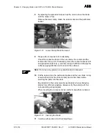
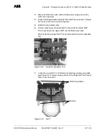
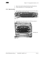
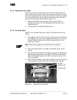
Pull the broken thyristor out of the plastic guide.
Figure 9-8 Removing a Thyristor
5
Remove the gate wires from the broken thyristor.
9.4.2
Treating a New Thyristor before Installation
1
Check the contact surfaces for nicks, scratches, bulges and surface
finish (flatness and roughness).
2
Connect the gate wires to the new thyristor.
3
Using a nylon sponge, carefully abrade the mating surfaces by
applying circular movements.Take special care not to expose the
copper when abrading. Wipe the abraded semiconductor surfaces
clean with methanol liquid and non-flammable cloth and apply a thin
layer of heat-conducting compound (G 322 L) on the mating surfaces
with a rubber trowel.
9.4.3
Mounting a New Thyristor
1
Push the semiconductor into the plastic guide.
Pay attention to the right polarity.
2
Tighten clamp bolts by hand.
3
Using a sliding caliper, verify that the distance between the deflection
bar and the outer cooling element is equal on both sides (see
Figure 9-4).
4
Place the deflection gauge in the middle of the clamp (see
Figure 9-5) and reset the dial to zero.
5
Tighten both screws alternately, first turning them half a turn each,
then less, until the desired compression force is reached (see
Figure 9-9 for the correct value).
6
Connect the gate wire to the pulse transformer.
7
Fasten the gate wires with a cable tie.
8
If a defective part has to be returned to ABB, particularly if it is still
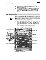
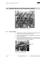
Plastic guide
Top view!
Fuse

