background image

Chapter 8 - Checking I/O 

ABB


48 (of 62)   

3BHS135824 ZAB E01Rev. D   ACS 6000 Commissioning Manual


8.3.4 

Serial Data Communication 

Connection of the ACS 6000 to a higher level automation system is 

typically done via a fieldbus adapter. The signals can be tested, when 

the auxiliary supply of the converter is on and the main and excitation 

supply is off. Confirm with automation commissioning personnel / 

customer that interface operates as intented. 


Follow the checklist of the I/O signals in the commissioning report. 


Summary of Contents for ACS 6000

Page 1: ...ABB ABB Switzerland Ltd All Rights Reserved ACS 6000 Medium Voltage AC Drives Commissioning Manual Document No 3BHS135824 ZAB E01Rev D Issued 05 10 2004...

Page 2: ...industrial property protection right Misuse in particular duplication and forwarding to third parties is not permitted This document has been checked with due care and attention However should the us...

Page 3: ...ction of Installation 13 3 1 Main Circuit Breaker MCB 13 3 2 Transformer 13 3 3 Converter 13 3 3 1 Ambient Conditions 14 3 3 2 Dimensions and Clearances 14 3 3 3 Installation Place and Cable Ducts 14...

Page 4: ...n 43 7 2 4 DDCS Communication 43 7 3 Limiter Parameters 43 7 3 1 Dynamic Torque Limiters and VLU RBU Settings 43 7 3 2 Gray and Pulse Encoders 44 Chapter 8 Checking I O 45 8 1 Checking Principle 45 8...

Page 5: ...Run 55 12 2 Final Tuning 55 Chapter 13 Speed Controller Tuning 57 13 1 Preliminary Tinung of Speed Controller 57 13 2 Final Tuning of Speed Controller 59 Chapter 14 Finishing the Commissioning 61 14...

Page 6: ...Table of Contents ABB 6 of 62 3BHS135824 ZAB E01Rev D ACS 6000 Commissioning Manual...

Page 7: ...ersions LxOC 3xxxx 1 2 Related Documents 3BHS125195 SigParACS6000 ARU_LNACxxxx Technical Note ACS 6000SD VC SW Commissioning Manual 3BHS120865 SigParACS6000AD_SD_INU Technical Note ACS 6000AD TC SW Co...

Page 8: ...nsulation test of cables transformers and motor can be made by the commissionig engineer In that case one additional day per motor drive combination needs to be reserved After insulation test the main...

Page 9: ...g loop Remote control cabling 12 Cabling of options transformer motor protection tachometer etc 13 Auxiliary voltage supply is available 14 The plate of the grounding switch lock override is attached...

Page 10: ...er Commissioning of MCB protection relays Adjusting and tuning of external devises like sensors switches 1 8 Commissioning Report While commissioning the ACS 6000 the commissioning report must be fill...

Page 11: ...be reported according to the list in the commissiong report Manufacturer information manufacturing identification and rating plate data of the installed components MCB transformers converters and moto...

Page 12: ...of any damage it must be reported to the carrier s representative and to ABB and or ABB representative Any damage during transportation or installation must be photographed and reported to the manufac...

Page 13: ...irements and fulfills the local regulations For details see the MCB documentation and document Main Circuit Breaker Specification document number 3BHS125149 Follow the checklist of the commissioning r...

Page 14: ...s etc must follow the local requirements in each country 3 3 3 Installation Place and Cable Ducts The floor must be of non flammable material with smooth and non abrasive surface protected against hum...

Page 15: ...and motor are shown in the ACS 6000 User s Manual Appendix D Electrical Drawings Project specific cable entries are indicated in Appendix F Mechanical Drawings Note The incoming cables must not touch...

Page 16: ...cables and control cables must not be located on the same cable trays A minimum distance between these cables is 30 cm Make sure that the cable entry and termination is done as required Special cauti...

Page 17: ...Power Ground as described above 5 The cross section of the cable shields must be in accordance with the Power Cable Specification document number 3BHS125090 6 Control cable shields must be earthed as...

Page 18: ...phase conductor Refer to the ACS 6000 User s Manual Chapter 9 Electrical Installation section Busbars and Grounding and the Power Cable Specification document number 3BHS125090 Follow the checklist o...

Page 19: ...moved The air conditioning of the room must be in operation Requirements for ambient temperature cooling water and converter room can be found on the rating plate of the ACS 6000 Before any test is ca...

Page 20: ...Chapter 3 Inspection of Installation ABB 20 of 62 3BHS135824 ZAB E01Rev D ACS 6000 Commissioning Manual...

Page 21: ...f the manufacturer The must have the following features 1 closing shunt release ON coil 2 opening shunt release OFF coils Installation of only 1 opening coil is not recommended 1 undervoltage release...

Page 22: ...or All valves must be in open position to allow free oil flow between tank and radiators Condition of dehydrating breathers Sense of rotation of fans and pumps if applicable Protection devices of tran...

Page 23: ...gnals Quality and flow rate of the cooling water Visual check of the instrumentation Instruments and cooling fans are shown in the circuit diagram of the motor auxiliaries Operation of these devices w...

Page 24: ...Chapter 4 Commissioning Other Drive Components ABB 24 of 62 3BHS135824 ZAB E01Rev D ACS 6000 Commissioning Manual...

Page 25: ...OU cabinet When finished check off the above mentioned items in the commissioning report The supportline must be informed if any changes have been made 5 2 Connecting the Auxiliary Supply Normally the...

Page 26: ...instructions in the Operation and Maintenance Manual in Appendix A Water Cooling Unit of the ACS 6000 User s Manual when filling and starting up the water cooling system Related parameter settings and...

Page 27: ...uring range of the output pressure sensors The measuring rangemay vary depending on the type of the WCU The measuring range of the sensors is given in the component list of the WCU Parameter 33 20 EOF...

Page 28: ...Chapter 5 Preparing the Converter ABB 28 of 62 3BHS135824 ZAB E01Rev D ACS 6000 Commissioning Manual...

Page 29: ...The insulation test of the ACS 6000 drive system is carried out with a test voltage of 5 kV DC Since the insulation resistance of a mult drive converter may be as low as 0 5 M a megger with a current...

Page 30: ...described in the following chapters The preparation described in this manual refers to insulation measurement which is carried out with 5kV DC voltage For high voltage tests additional preparation wi...

Page 31: ...oning Manual 3BHS135824 ZAB E01Rev D 31 of 62 Type 3 Grounding switch must be open 6 2 2 LSU Preparation The following preparatory measures must be taken in aLine Supply Unit LSU DC_plus DC_NP DC_minu...

Page 32: ...d connect it to ground X715 9 10 Note that the earthing isolator must be in position NOT EARTHED 2 Short circuit and ground the coil of the charging relay K2CHU X714 1 2 3 Ground the primary side of t...

Page 33: ...l resistor 6 2 4 ARU INU Preparation The following preparatory measures must be taken in an Inverter Unit INU The same instructions apply to an Active Rectifier Unit ARU if present in the line up GU G...

Page 34: ...B E01Rev D ACS 6000 Commissioning Manual ABB 3BHE006414R0001 XV C770 AE ABB 2 Disconnect and ground all three LEM current transducers on CVMI board ADCVI board in older drive versions x1 x8 x7 x6 x4 x...

Page 35: ...C voltage The plus terminal is connected to the combined circuit of the DC link The minus terminal is connected to the ground potential The measurement time is 60 sec The lowest value is to be recorde...

Page 36: ...of board A6033 8 Disconnect inputs P and N of power supply G6041 9 Short circuit and ground the 24V output on terminal blocks X66 and X68 10 Disconnect and isolate terminals 5 9 20 22 of MR 627 A6041...

Page 37: ...Measurement is carried out with 1 kV DC voltage and a measurement time is 60 sec The plus terminal is connected to the combined circuit of output and three input terminals The minus terminal is conne...

Page 38: ...Chapter 6 Insulation Resistance Measurement ABB 38 of 62 3BHS135824 ZAB E01Rev D ACS 6000 Commissioning Manual...

Page 39: ...activated etc Note If the drive does not proceed to the ReadyOn state check the condition and proper connection of the PPCS communication fibers and the condition of all the control HW boards Check a...

Page 40: ...eed 1 2 dertermine the reference for the inching speed applicable for metals applications Parameter Group 24 Speed Control Parameters goup 24 provides all settigs for speed controller tuning At this s...

Page 41: ...2 is used for load sharing function between two drives in speed control mode e g hot rolling mill top and bottom motor Parameter Group 50 Speed Measurement Parameter 50 1 Speed Scaling defines the sca...

Page 42: ...e g AC110 Both are connected to channel 0 of the AMC board If an AC 80 Advant controller is part of the converter CIU option the overriding system can communicate via this controller which is linked t...

Page 43: ...k control of channel 4 are made in parameter group 70 Check that parameter 70 3 CH0 Baud Rate is set to 4 Mbit s 7 3 Limiting Parameters 7 3 1 Dynamic Torque Limiters and VLU RBU Settings There are th...

Page 44: ...lowing parameters are needed for encoder initialization Parameter Name Unit 165 23 Pulse number of the speed encoder NTAC pulse number pulses rev 165 30 Selection if the used speed encoder has zero ch...

Page 45: ...or should be changed Checking of binary input signals is done by changing the state of each input in process side that is CBs contactors etc If state of switch can not be changed test is done from the...

Page 46: ...is an optical link between all INT and PINT boards Power Forward Link in case of multidrive configuration Status indication of both door monitoring and doorlock monitoring signals of each medium volt...

Page 47: ...hermistor relays Oil transformers may also have Pt 100 measurements for oil temperature supervision Later when main circuit breaker control is checked also gas relay s opening of main circuit breaker...

Page 48: ...a higher level automation system is typically done via a fieldbus adapter The signals can be tested when the auxiliary supply of the converter is on and the main and excitation supply is off Confirm w...

Page 49: ...ioning Manual must be followed 9 1 Energizing the Drive In the ACS 6000 converter charging of the intermediate DC link is done from auxiliary power supply by means of a charging transformer This allow...

Page 50: ...external emergency OFF Check that the MCB control works properly that feedback signals comes correctly to the SW and DC is discharged with VLU RBU Charge and close the MCB again and open this time by...

Page 51: ...in case of incorrect rotation direction of the motor 10 1 1 First Start up with No Load When doing the first start one should keep in mind that in order to prevent the unnecessary rushing of the motor...

Page 52: ...Chapter 10 ACS 6000ad Start up ABB 52 of 62 3BHS135824 ZAB E01Rev D ACS 6000 Commissioning Manual...

Page 53: ...citation current control can be activated when ARU is in MODULATING state INU control at READY RUN state 11 2 Motor Idle Run Prior to the first start the absolute encoder has to be positioned Using fo...

Page 54: ...ent For avoiding the possible motor rushing during first start special first start mode can be used See ACS 6000AD TC SW Torque Controller Software commissioning manual for detailed instructions Befor...

Page 55: ...equire mechanical heat run In mechanical heat run the speed is increased step by step to maximum during few hours and at the same time bearing temperatures etc are measured Note After motor is coupled...

Page 56: ...Chapter 12 ACS 6000 Final Tuning ABB 56 of 62 3BHS135824 ZAB E01Rev D ACS 6000 Commissioning Manual...

Page 57: ...iven process The main requirement is not to make the control as fast as possible but only fast enough to make the changes required by the process without conflicting with other control loops Too fast...

Page 58: ...datalogger and apply steps Tuning is done by using AMC parameters 121 01 KPS which is proportinal gain and 121 05 TIS which is integration time of speed controller After speed controller has been tune...

Page 59: ...en next but methods other than those presented in this chapter can also be used Speed steps of 2 of maximum speed or bigger are applied to see the response behaviour of actual speed See instructions f...

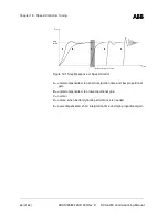
Page 60: ...e Step height A Error Time B C D E Figure 13 1 Step Response of Speed Control A undercompensated too short intergration time and low proportional gain B undercompensated too low proportional gain C no...

Page 61: ...k up Read all the parameters from the drive by using DrivesWindow program and save them into a file Be sure that all parameter groups are open and that all parameter values are saved properly In Drive...

Page 62: ...part 14 6 Documents and Back up Copies MV AC Supportline address below Commissioning report preferably as file Parameter back up files Travel report Warranty reports of replaced components if any to...

Reviews: