background image

CONTROL SYSTEM

PRODUCT

ACS1000W

DOCUMENT KIND

User manual

DOCUMENT ID.

3BHS213400 E01

REV.

J

LANG.

en

PAGE

56/166

4.2.2.7. Operating modes

The drive provides the following operating modes:

Master-follower operating mode:

 used for applications with several drives 

where the motor shafts are coupled to each other (eg, gearing, chain, belt). 
Owing to the master- follower operating mode the load can be evenly 
distributed between the drives or at some adjustable other ratio which 
depends on the process.

Hand-auto operating mode:

 suitable for applications where the speed has to be 

controlled automatically by a process automation system and manually by an 
external control panel. The active control station is selected via a digital input.
The operating mode is also recommended when two external control stations 
exist from where the reference value can be set and the drive can be started 
and stopped. The external control station is selected via a digital input.

4.3. I/O interfaces

4.3.1. IOEC I/O modules

Internal and external, analog and binary I/O signals are connected to the control 
system by IOEC modules.
The standard I/O includes one external module (IOEC 2, IOEC 3) and one module 
that is internal to the drive operation (IOEC 1). The standard I/O provides standard 
control and supervision functionalities sufficient for most applications.
The drive can include an optional expansion I/O that includes an external module 
(IOEC 4). These expansion modules provide extra inputs and outputs for control 
and supervision as may be required by the drive or the customer to support various 
control options.

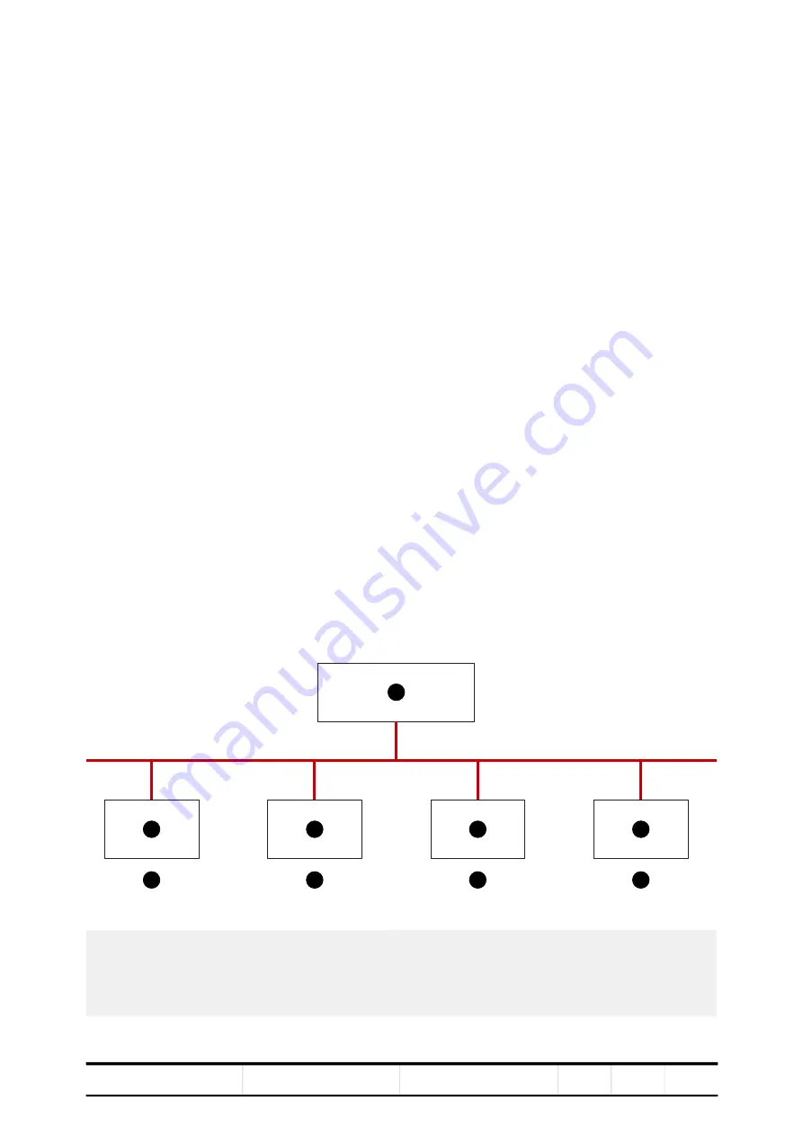
Figure 4

-

7 IOEC interfaces overview

1) IOEC 1
2) IOEC 2
3) IOEC 3
4) IOEC 4

5) AMC circuit board
6) Standard
7) Option

1

2

3

4

5

6

6

7

7

Summary of Contents for ACS1000

Page 1: ... cooled User manual OWNING ORGANIZATION ABB Switzerland Ltd DATE 2021 11 17 STATUS Approved SECURITY LEVEL Public DOCUMENT KIND User manual DOCUMENT ID 3BHS213400 E01 REV J LANG en PAGE 1 166 Copyright 2009 ABB All rights reserved ...

Page 2: ...ding but not limited to the installation of firewalls application of authentication measures encryption of data installation of antivirus programs and so on to protect these products the network its system and interfaces against security breaches unauthorized access interference intrusion leakage and or theft of data or information Any liability of ABB in this regard is excluded ABB may perform fu...

Page 3: ...y labels 22 2 4 General safety instructions 23 2 5 The 7 steps that save lives 24 2 6 Possible residual risks 26 2 7 Main circuit breaker protection device 27 2 7 1 Safety and protection requirements 28 2 7 2 Minimum requirements for MCB and MCB control 28 2 8 Maintenance recommendation 29 3 Power electronics and cabinet features 31 3 1 Overview 31 3 2 Main components of the drive system 32 3 3 Po...

Page 4: ...5 2 Storing the drive 67 5 5 3 Storage and handling of spare parts 68 5 6 Disposal of packaging materials and components 68 6 Mechanical installation 69 6 1 Safety 69 6 2 Overview of installation work 69 6 3 General notes on installation 69 6 3 1 Dimensions and clearances 69 6 3 2 Cabinet roof 69 6 3 3 Fire protection 70 6 3 4 Cable duct material 70 6 4 Preparing the floor 70 6 5 Fixing the cabine...

Page 5: ...ation checklist 104 8 2 2 Electrical installation checklist 104 8 2 3 Main circuit breaker MCB 105 8 2 4 Input transformer checklist 105 8 2 5 Motor checklist 105 8 2 6 Insulation tests checklist 105 8 2 7 Power supply checklist 106 8 2 8 Miscellaneous checklist 106 9 Operation 107 9 1 Safety 107 9 2 Overview 107 9 3 Operating conditions 107 9 4 Sound pressure level 107 9 5 Local operator panel 10...

Page 6: ...2 3 Understanding wiring diagrams 142 11 3 Alarm fault indications 143 11 3 1 Messages 143 11 3 2 Error message levels 143 11 3 3 Fault handling 144 11 3 4 Standard troubleshooting procedure 145 11 4 Removing the CDP control panel 146 11 5 LEDs and switches on circuit boards 147 11 5 1 AMC circuit board 147 11 5 2 IOEC I O modules 148 11 6 Corrective maintenance 149 11 6 1 Safety 149 11 6 2 De ene...

Page 7: ...oltage and current waveforms at drive output 38 Figure 3 9 Rectifier and inverter compartment 39 Figure 3 10 Three level voltage source inverter principle 40 Figure 3 11 ACS1000W water cooled with braking chopper 1 40 Figure 3 12 Principle diagram 41 Figure 3 13 Braking chopper design 42 Figure 3 14 Door locks 45 Figure 3 15 IAC label example 46 Figure 3 16 Door bolts 46 Figure 3 17 Optional space...

Page 8: ...able ties B 84 Figure 7 9 Example of busbars with cable spacers cable entry top 85 Figure 7 10 Cable entry top for motor side and line side cable entry A and cable routing B 86 Figure 7 11 Cable entry bottom for motor side and line side cable entry A and cable routing B 87 Figure 7 12 Additional cable routing options cable entry top for motor side and cable entry bottom for line side A and cable e...

Page 9: ...Figure 11 1 Device identification 142 Figure 11 2 AMC circuit board 147 Figure 11 3 IOEC module 148 Figure 11 4 Location of I O modules and fuses 153 Figure 11 5 Cleaning and replacing filter mats 158 Figure 11 6 Control compartment battery location 159 Figure 11 7 Control compartment replacing the batteries 160 Figure 11 8 Water cooling unit Replacing the internal fan 161 Figure 11 9 Water coolin...

Page 10: ......

Page 11: ...g ratings 43 Table 3 2 Cabinet dimensions and weight 44 Table 3 3 Braking resistor cables 44 Table 3 4 ABB arc resistant classes 46 Table 4 1 IOEC module configuration analog inputs 57 Table 4 2 IOEC module configuration analog outputs 57 Table 4 3 IOEC module configuration digital inputs 57 Table 4 5 24 V internal voltage supply 58 Table 4 4 IOEC module configuration digital inputs 58 Table 4 6 I...

Page 12: ......

Page 13: ... included in this document Appendix A Additional manuals provides manuals about additional equipment delivered with the drive such as project specific options such as pulse encoder or fieldbus interfaces or information on modifications of the standard drive Appendix B Technical data contains the technical data sheets of the drive Appendix C Mechanical drawings provides the outline drawings of the ...

Page 14: ...al fibers Drive Short form for ACS1000W drive Drive system The drive system includes all equipment used to convert electrical into mechanical power to give motion to the machine DriveBus Communication link dedicated for ABB drives DriveDebug DriveDebug is part of ABB s DriveWare software tools for drives using the DDCS communications protocol DriveDebug runs on computers with Windows operating sys...

Page 15: ... The industrial customer is responsible not to distort voltage and current by its electrical systems PID controller Proportional integral derivative controller Control loop feedback system for controlling process variables eg pressure flow PE Protective earth PPCS Power plate communication system PPCS is an acronym for a serial communication protocol designed for data transfer via optical fibers b...

Page 16: ...HS853483 E02 Fixing Lifting details ACS1000W Seismic 3BHS853483 E03 Table 1 5 Specifications and guidelines Title Document number Retrofit guideline 3BHS301179 E01 Input circuit breaker engineering guideline 3BHS104785 E01 Main transformer specification 3BHS356582 E01 Induction motor specification 3BHS260163 E01 Power cable specification 3BHS189994 E01 Power cables engineering guideline 3BHS542290...

Page 17: ... be performed by qualified and certified ABB personnel 1 5 1 Handling The personnel must be skilled and experienced in unpacking and transporting heavy equipment 1 5 2 Mechanical installation The personnel must be qualified to prepare the installation site according to the site and equipment requirements and to perform the installation accordingly 1 5 3 Electrical installation The personnel must h...

Page 18: ...ibility of those in charge of the drive to ensure that each person involved in the installation operation or maintenance of the drive has received the appropriate training and has thoroughly read and clearly understood the instructions in this manual and the relevant safety instructions 1 7 Intended use of equipment Those in charge of the drive must ensure that the drive is only used as specified ...

Page 19: ...ard code for electrical work safety ISO 13849 1 Safety of machinery Safety related parts of control systems Part 1 General principles for design section 6 2 6 Category 3 IEC 60204 1 Safety of machinery Electrical equipment of machines Part 1 General requirements IEC 60721 3 1 Classification of environmental conditions Classification of groups of environmental parameters and their severities Storag...

Page 20: ...ig 1 1 which contains the user manual and related documents Strain relief rails Air exhaust hood Redundant fan unit option Set of bolts nuts and washers Figure 1 1 Delivered items For a complete list of the items in the delivery see the shipping note 1 10 Identifying the delivery The drive and accessories are identified by the type code printed on the rating label The label provides information on...

Page 21: ...g on or around the equipment Failure to do so can result in serious Injury or DEATH Keep for future reference This is the safety alert symbol It is used to alert you to potential physical injury hazards Obey all safety messages that follow this symbol to avoid possible injury or death DANGER Indicates a hazardous situation which if not avoided will result in death or serious injury WARNING Indicat...

Page 22: ...y warning This sign can also have additional text below it eg High voltage Hot surface Crushing of hands No access for people with active implanted cardiac device The magnetic field of the drive can influence the functioning of pacemakers The pacemaker sign should be installed at the entrance to the drive room or at a minimum distance of 6 m from the drive to stop personnel with pacemakers approac...

Page 23: ...l safety hazards Wear hearing protection when a drive is running 4 While working on the drive DO NOT step on the roof DO NOT install foreign objects on the roof 5 Before working on a water cooling unit WCU In addition to the safety instructions for working on a drive always read the WCU safety data sheet for relevant safety information eg the type of ion exchange resin and glycol 6 Before working ...

Page 24: ...nal Protective Equipment PPE Decide of the appropriate work methods and initiate the Permit To Work PTW process 2 Clearly identify the work location and equipment Use your senses sight hearing and smell to identify problem areas Define the work area via barriers and barricading and label equipment Avoid distractions such as talking or texting on the phone 3a Disconnect all sources of supply If ABB...

Page 25: ...nd short circuiting If this is carried out by the customer then the PICW must ensure that this equipment is properly earthed as a part of the integration verification and during step 7 when the PICW walks the PTW 6 Protect against adjacent live parts and take special precautions when close to bare conductors Determine minimum approach distances apply screening or shrouding and when applicable padl...

Page 26: ...orrectly assembled or installed equipment Wrongly connected cables External influence on or damage of the equipment Wrong parameter settings Software errors Faulty hardware 3 Hazardous touch voltages can be present on drive system components which can be caused by Operation of the equipment outside the scope of the specifications External influence on or damage of the equipment Induced voltages by...

Page 27: ...d further damage to the equipment The MCB is located on the primary side of the converter transformer Figure 2 2 Drive system overview NOTE MCBs and protection relays are not included in the drive supply Typical MCBs devices Vacuum circuit breakers SF6 circuit breakers Fused contactors or motor control centers Dedicated protection relay Transformer or drive primary cable protection DTL Transformer...

Page 28: ...to wire the trip command through any PLC or DCS system if it is not certified to meet SIL three level requirements and to fulfill the timing requirements outlined below Opening of the MCB by the drive must be possible at any time It is not permitted to interrupt the open and or trip command eg by a local remote switch in the MCB When the MCB is in service position the drive must have exclusive con...

Page 29: ...ontrol voltage Upstream protection coordination scheme is provided which uses the breaker failure ANSI 50BF signal to automatically trip the upstream breaker in case the MCB does not open IMPORTANT The upstream breaker must open within the maximum safety trip time after a failure has occurred 2 8 Maintenance recommendation The MCB trip circuits should be checked annually 1 Short circuit occurs 2 O...

Page 30: ......

Page 31: ...rmer for the control of standard induction motors For information on the power and voltage range of the drive see the technical specifications and the rating plate of the drive The following sections provide an overview of Drive topology and main features Available main and auxiliary power configurations Power electronic components of the drive Cooling system Cabinet features such as the grounding...

Page 32: ...sists of the following main components Main circuit breaker MCB For more information see Section 2 7 Main circuit breaker protection device Transformer For more information see the Main transformer specification 3BHS356582 E01 Drive Asynchronous motor For more information see the motor specification 1 Medium voltage switchgear including main circuit breaker and transformer protection 2 Transformer...

Page 33: ...for the control and cooling system Figure 3 3 Drive overview with power supplies 3 3 1 Main power supply configurations The drive is connected to the main power supply via a three winding oil or dry type transformer 1 Auxiliary power supply 2 ACS1000W 3 Control and cooling system 4 Auxiliary power distribution 5 Cooling system 6 Control system 7 Main power supply 8 MCB 9 Transformer 10 Power elect...

Page 34: ...ol system thus enabling the drive to ride through and or to perform a controlled shutdown Through separate power supplies The auxiliary power is supplied to the drive by a three phase AC power supply and by an UPS to a separate one phase AC or DC input Feeding the control power separately by an UPS has the advantage that the main control hardware will remain energized the full ride through capabil...

Page 35: ...ology This section describes the main design features and introduces the major power electronics components of a typical drive 3 4 1 Overview Figure 3 4 ACS1000W 1 Control and terminal compartment 2 DC link and filter compartment 3 Rectifier and inverter compartment 4 Water cooling compartment 5 Cabinet with second 12 pulse rectifier 1 2 3 4 5 A B ...

Page 36: ...stem of the drive For more information on the control hardware see Chapter 4 Control system Terminal compartment 2 in Fig 3 5 the terminal compartment in the back contains the busbars for the feeder and motor cables the ground cable and the cable screens A hinged bolted partition separates the terminal compartment from the control compartment For more information on cable entry and cable connectio...

Page 37: ...NT KIND User manual DOCUMENT ID 3BHS213400 E01 REV J LANG en PAGE 37 166 3 4 3 DC link and filter compartment Figure 3 6 DC link and filter compartment 1 Filter capacitors 2 Grounding switch 3 Filter choke 4 DC link capacitors 5 Common mode choke option 5 1 2 3 4 ...

Page 38: ...ged When the voltage is below 50 V DC the lamp grounding switch unlocked 1 in Fig 3 7 on the door of the control compartment lights up and the grounding switch can be turned to position grounded 2 in Fig 3 7 Figure 3 7 Grounding switch When the grounding switch is in position grounded the doors of the medium voltage compartments are released and the doors can be opened 3 4 5 Filter The filter at t...

Page 39: ... output to the minus neutral point and plus side of the DC link Depending on the harmonics requirements for the main power supply the drive is equipped with a 12 pulse or a 24 pulse rectifier 3 4 6 2 Protection IGCTs The drive features a fuseless protection design The IGCTs are placed between the rectifier and the DC link If necessary the IGCTs directly isolate the inverter from the main power sup...

Page 40: ...ect torque control For more information see Section 4 2 2 4 Direct torque control Figure 3 10 Three level voltage source inverter principle 3 4 7 Optional Braking Chopper The optional braking chopper uses resistor braking to provide motor braking and shorter deceleration times eg for Reduction of coasting down time eg for conveyor belts fans and pumps Emergency stops The braking chopper cabinet co...

Page 41: ... FEATURES PRODUCT ACS1000W DOCUMENT KIND User manual DOCUMENT ID 3BHS213400 E01 REV J LANG en PAGE 41 166 Figure 3 12 Principle diagram 1 Rectifier 2 Braking chopper 3 Inverter 4 Braking resistor 1 2 3 4 Rb VC1 VC2 VCs2 VCs1 C2 C1 ...

Page 42: ...tifier of the ACS1000W Figure 3 13 Braking chopper design 3 4 7 2 Monitoring and protective functions Current monitoring Input currents of the braking chopper are monitored for overcurrent and imbalance in order to detect any defective component in the circuit The current can become imbalanced if one of the IGCTs conducts a current permanently or if an IGCT fails to be switched on If a short circu...

Page 43: ... and must not be greater than 2 5 MW Table 3 1 The relation between maximum braking energy Ebrake max and maximum chopper braking power Pchopper max is as follows 1 After a braking period of 30 s with maximum braking power 2 5 MW a cooling time of one hour is required If two braking sequences of 30 s are necessary within an hour the maximum braking power has to be reduced to 50 of the maximum poss...

Page 44: ...lying a cabinet design consisting of folded galvanized sheet metal plates approximately 2 mm thick and minimizing the space between the rivets The inside walls of the cabinet are not painted because paint tends to reduce the effectiveness of metallic bonding which is important for successful EMC Accordingly only the front of the cabinet is painted while all other walls are galvanized However the c...

Page 45: ...tion 11 6 2 De energizing the drive locally 3 6 1 Optional cabinets If medium voltages are present in an optional cabinet during operation eg braking chopper and output disconnector the door is secured by an electro mechanical lock as well as a door monitoring switch If the cabinet is UL certified the door is further secured with extra screws The lock and the switch release the door after the DC l...

Page 46: ...ing plate on the control compartment door of the drive Figure 3 15 IAC label example 3 7 2 Power compartment doors As part of the arc resistant design of the drive the doors of the power compartments must be secured with bolts and washers which are in a bag Fig 3 16 in the loose parts box The drive frame has captive nuts for the bolts Figure 3 16 Door bolts Table 3 4 ABB arc resistant classes ABB ...

Page 47: ...very ie a main circuit breaker For more information on the MCB MCB overview Section 2 7 Main circuit breaker protection device MCB requirements Input circuit breaker engineering guideline 3BHS104785 E01 3 8 Space heaters The optional space heaters protect the cabinet from condensation The drive switches on the space heaters when the cooling system is switched off Figure 3 17 Optional space heaters...

Page 48: ......

Page 49: ... control devices Depending on the control concept of the drive system the remote control devices include a higher level control system and or remote operator stations Figure 4 1 Block diagram of control system with customer interface A control system B and power electronics C 1 ABB Ability 2 Higher level control system 3 Fieldbus 4 DDCS 5 RS485 6 CDP control panel 7 PC tools 8 AMC circuit board 9 ...

Page 50: ...tion Figure 4 2 Control compartment For information on the devices present in the control compartment see Appendix D Wiring diagrams For information on the transformer protection see Appendix A Additional manuals 1 Control power supply 2 AMC circuit board and INT circuit board 3 Pulse encoder option 4 Fieldbus interface option 5 IOEC1 module 6 Motor starters and circuit breakers 7 Control power su...

Page 51: ...artment see Appendix D Wiring diagrams 4 2 1 Local control panel The local control panel on the door of the control compartment serves as the basic user interface for monitoring control operation of the drive and setting of parameters For more information see Chapter 9 Operation and Chapter 10 CDP control panel 1 IOEC2 module standard 2 IOEC4 module option 3 Auxiliary voltage terminals 4 IOEC3 mod...

Page 52: ...tasks The AMC circuit board has specific control and closed loop tasks assigned to it It processes drive and status information performs the speed and torque control tasks and monitors the operation of the drive All relevant drive variables eg speed torque current voltage are continuously monitored by the control system Pre programmed protection functions ensure that these variables remain within ...

Page 53: ...ix G Signal and parameter table 4 2 2 3 Main circuit breaker The main circuit breaker MCB is an important switching and protection device of the drive system Therefore it must only be controlled and monitored by the drive For more information see Input circuit breaker engineering guideline 3BHS104785 E01 Main circuit breaker protection device page 27 4 2 2 4 Direct torque control The speed and tor...

Page 54: ...transfer to a higher level control system see Section 4 3 2 Serial communication interface fieldbus Pulse encoder interface NTAC option see Section 4 3 3 Pulse encoder interface NTAC option PC based service tools comprising DriveWare software tools commissioning and maintenance tools ie DriveWindow and DriveDebug and DriveOPC for data transfer between ABB drives and Windows based applications NETA...

Page 55: ...erent acceleration and or deceleration settings in addition to an adjustable speed reference value Up to seven constant speed settings and two acceleration and or deceleration settings are possible The selection of the different settings can be automated by a process control system or can be made manually by selector switches that are connected to the corresponding digital inputs of the drive The ...

Page 56: ...ommended when two external control stations exist from where the reference value can be set and the drive can be started and stopped The external control station is selected via a digital input 4 3 I O interfaces 4 3 1 IOEC I O modules Internal and external analog and binary I O signals are connected to the control system by IOEC modules The standard I O includes one external module IOEC 2 IOEC 3 ...

Page 57: ...er Input resistance Rin 105 Ω for current input Rin 250 k Ω for voltage input Common mode voltage Maximum 48 V Isolation level 350 V AC Table 4 2 IOEC module configuration analog outputs No of I O 2 Signal range 0 20 mA load impedance max 250 Ω Resolution 12 bit Isolation level 350 V AC Table 4 3 IOEC module configuration digital inputs No of I O 14 Signal level 22 120 V DC 1 22 250 V AC 1 For the...

Page 58: ...cted by a PTC resistor against short circuit and external applied overvoltages Table 4 4 IOEC module configuration digital inputs No of I O 6 Signal level Maximum 120 V DC or 250 V AC Isolation level 4000 V AC Switching capacity Voltage Switching current Steady state current 24 V DC 8 A 6 A 24 V AC 8 A 6 A 48 V DC 1 A 6 A 48 V AC 8 A 6 A 120 V DC 0 4 A 6 A 120 V AC 8 A 6 A 230 V AC 8 A 6 A Table 4...

Page 59: ...E ADDRESS DO1 DO2 DO3 X11 1 X11 2 DI1 X11 3 X11 4 DI2 X11 5 X11 6 DI3 X11 7 X11 8 DI4 X11 9 X11 10 DI5 X12 1 X12 2 DI6 X12 3 X12 4 DI7 X12 5 X12 6 DI8 X12 7 X12 8 DI9 X12 9 X12 10 DI10 X13 1 X13 2 DI11 X13 3 X13 4 DI12 X13 5 X13 6 DI13 X13 7 X13 8 DI14 DI1 DI2 DI3 DI4 DI5 DI6 DI7 DI8 DI9 DI10 DI11 DI12 DI13 DI14 24 VIR OVIR V IR OK OFF ON X13 9 X13 10 AI1 OV AI2 AI3 AI4 AO1 AO2 AI1 10V AI2 AI3 AI4...

Page 60: ...ng diagram as can be seen in Fig 4 9 The letter A represents the kind of part we have an assembly the next three digits are the page number the part is located on page 191 and the last digit 1 means that our part is the first assembly on the page This identification label number is the key to track electrical devices throughout the drive and in the ABB documentation The designation for each IOEC m...

Page 61: ...ce in the drive see Appendix D Wiring diagrams For more information on the device consult the relevant manual Modbus TCP Ethernet NETA 21 remote monitoring tool user manual 3AUA0000096939 Modbus RTU Modbus NMBA 01 installation and start up guide 3AFY58919772 Profibus Profibus NPBA 12 installation and start up guide 3BFE64341588 DeviceNet DeviceNet NDNA 02 installation and start up guide 3AFY589198...

Page 62: ...if pulse encoder feedback is used to control the motor For more information on the device see Installation and start up guide for the pulse encoder module NTAC 0x 3AFY58919730 Figure 4 10 NTAC 02 pulse encoder interface Terminals X1 Terminals X2 1 A Channel A 1 V 0 V 2 A 2 V 24 V 3 B Channel B 3 V 4 B 4 24 25 5 Z Channel Z 5 15 6 Z 6 24 7 SH Shield 7 0 V 8 SH 8 24 V A X1 X2 B B B SH SH Z A 24V 24 ...

Page 63: ...rt time 2 months 5 3 Unpacking and inspection 1 Remove all packaging material carefully 2 Check the drive and accompanying equipment for damages 3 Compare the complete delivery with the purchase order and the packing list 4 If parts are missing or damaged immediately inform the shipping company and the ABB service organization NOTE It is recommended to photograph the damages and send the photograp...

Page 64: ...s arrows The rails can be removed after the cabinet has been installed at its final location To attach a sling use appropriate safety hooks or shackles NOTICE Risk of component damage DO NOT lift and move the drive or a transport unit using a forklift The frame of the cabinets could be damaged If a crane is not available contact ABB for instructions on other means of moving Transport the cabinet i...

Page 65: ...65 166 Maximum slope angle is 60 1 in Fig 5 1 Figure 5 1 Transporting the cabinet by crane standard case Lift the cabinet slowly and steadily to the required clearance height maintaining the cabinet in upright position Check the horizontal position of the cabinet and reposition the slings if necessary 1 Slope angle 60 60 1 2 ...

Page 66: ...Fig 5 2 Do not pass a sling through the hole To attach a sling use appropriate safety hooks or shackles 2 in Fig 5 2 Maximum slope angle is 15 3 in Fig 5 2 Protect the edges of the cabinet 4 in Fig 5 2 Figure 5 2 Transporting the cabinet by crane marine offshore case Lift the cabinet slowly and steadily to the required clearance height maintaining the cabinet in upright position Check the horizont...

Page 67: ...r information contact the ABB service organization or add the appropriate amount of glycol for frost proofing if the drive is to be stored in ambient temperatures below 0 C For information on frost proofing see the user manual for the water cooling unit 2 Remove the batteries if applicable 3 Cover all cable inlets and ventilation slots with an impermeable plastic or aluminum foil and a wooden pane...

Page 68: ...ecautions before handling these devices Check the spare parts immediately after receipt for damage and report any damage to the shipping company and the ABB service organization Keep spare parts in their original packaging Store printed circuit boards in antistatic bags or boxes Storage temperature range 5 C 55 C Storage place requirements Free of vibration and shock Protected against dust sand ve...

Page 69: ...Mechanical drawings for information on Cabinet dimensions Clearances to be observed Mounting hole sizes 6 3 2 Cabinet roof The cabinet roof is not designed as a mounting base for eg foreign devices cable ducts Therefore it is not permitted to install any foreign device on the roof All installation work must be carried out by qualified personnel according to the site and equipment requirements and ...

Page 70: ...abinet Overall incline across 5 m must not exceed 5 mm Even Non flammable smooth and non abrasive Protected against humidity diffusion 6 5 Fixing the cabinet to the floor IMPORTANT If the doors of medium voltage compartments cannot be opened contact the ABB service organization Required layout drawings Refer to the relevant layout drawing for detailed instructions on how to fix the cabinet to the ...

Page 71: ...heck if the doors are misaligned NOTE If the doors do not open and close properly place leveling plates at the appropriate points arrows in Fig 6 1 Recommended size 80 x 300 x 0 5 mm Figure 6 1 Leveling the drive 3 Fix the cabinet to the floor according the relevant layout drawing see Required layout drawings page 70 NOTE Floor fixings are not supplied Figure 6 2 Location of screw holes in a stand...

Page 72: ...AL INSTALLATION PRODUCT ACS1000W DOCUMENT KIND User manual DOCUMENT ID 3BHS213400 E01 REV J LANG en PAGE 72 166 4 Remove the two shipping braces Keep the shipping braces for later use Figure 6 3 Shipping braces ...

Page 73: ... the second rectifier This section applies to 24 pulse drives if the cabinet with the 2nd rectifier is delivered separately 1 Attach the cabinet to the drive with the supplied screws 2 Connect the water tubes 1 and 2 in Fig 6 4 3 Connect the cables according to the wiring diagram Figure 6 4 Installing the cabinet with the second rectifier cabinet 1 2 ...

Page 74: ...n casing 3 and 4 in Fig 6 5 to the roof and with each other 3 Put the fan 5 in Fig 6 5 into the casing and fasten it to the vibration dampeners 6 in Fig 6 5 4 Route the power supply cable through the rectangular opening 7 in Fig 6 5 into the cabinet and connect it inside the terminal box 8 in Fig 6 5 5 Install the cover of the fan housing 9 in Fig 6 5 Figure 6 5 Installing the redundant fan 1 Lift...

Page 75: ...er cooling unit in Appendix A Additional manuals 6 9 Checking the door center posts The DC link and filter compartment and the rectifier and inverter compartment are equipped with center posts If a center post has been removed for installation purposes it must be installed again before the drive is energized The center posts are important for securely locking the doors Figure 6 6 Door center posts...

Page 76: ......

Page 77: ...ctor see Power cable specification 3BHS189994 E01 Power cables engineering guideline 3BHS542290 E01 For information on the requirements for the auxiliary power cable and the control cables see the Auxiliary power and control cables guideline 3BHS813742 E01 DANGER Hazardous voltage Improper work can result in DEATH or life threatening injury The electrical installation must be carried out by qualif...

Page 78: ...Protective Earth for grounding the armor and shields of the cables and for the connection of the ground cable To identify the ground bus see Appendix D Wiring diagrams Figure 7 1 Grounding the drive system 1 Input transformer 2 Drive 3 Motor 4 Earth electrode 5 Ground cable 6 Cable screen 7 Equipotential bonding conductor 8 Motor PE U V W PE 2U1 ACS1000 2V1 2W1 1U1 1V1 1W1 PE U2 V2 W2 U2 V2 W2 U1 ...

Page 79: ...s Cable entry with sealing modules type 1 Cable entry with sealing modules type 2 Cable entry with cable glands For information on location and dimensions see Appendix C Mechanical drawings 7 5 1 Cable entry with EMC plates Usage Power cables ground cables and bonding conductors Auxiliary power cables and control cables Included in delivery galvanized plate with net like EMC sleeves 1 in Fig 7 2 a...

Page 80: ...he cable entry is used for control cables Figure 7 3 EMC cushion 7 5 2 Cable entry with type 1 sealing modules Usage power cables ground cables and bonding conductors Included in delivery cable entry frame 1 in Fig 7 4 Not included in delivery sealing modules 2 in Fig 7 4 accessories and tools Figure 7 4 Type 1 sealing modules example 1 Cable entry frame 2 Sealing modules 1 1 2 2 ...

Page 81: ...d in delivery tools accessories and EMC sealing modules 2 in Fig 7 5 Supplier Roxtec AB www roxtec com Figure 7 5 Type 2 sealing modules example 7 5 4 Cable entry with cable glands Usage Power cables ground cables and bonding conductors Auxiliary power cables and control cables Included in delivery undrilled plate for cable glands Not included in delivery cable glands tools and accessories Figure ...

Page 82: ...vice identification 7 6 1 Preparing the cable entry the cable spacers and the cables 7 6 1 1 Maximum number of cables per phase The maximum number of cables that can be used per phase depends on the type of the drive and its nominal voltage NOTICE Risk of damage or malfunction Waste inside the cabinet can cause damage or malfunction If possible DO NOT cut cables inside the terminal compartment Ret...

Page 83: ...CS1000W DOCUMENT KIND User manual DOCUMENT ID 3BHS213400 E01 REV J LANG en PAGE 83 166 Figure 7 7 Busbars for 12 pulse drive B and 24 pulse drive A and B 1 PE ground busbar A B 2U1 4U1 4V1 4W1 3U1 3V1 3W1 2V1 2W1 U2 V2 W2 1U1 1V1 1W1 1 ...

Page 84: ... which depend on the way the motor side and line side cables are routed are shown in the mechanical drawing of the drive ie 3BHL000886 E02 NOTE For cables with twin hole cable lugs install the cables first then install the cable spacers over the attached cables 7 6 1 3 Determining the cable length 1 Determine the required length of a cable between the point of entry and the connection point inside...

Page 85: ...owing variants show the recommended routing for the maximum amount of cabling ie when the space in the terminal unit is limited Limits on the available space in the terminal unit are less critical if fewer cables are used The following images show the recommended cable routing for an ACS1000W W3 3 kV drive that has three cables per phase 1 Cable spacer 2U1 1V1 1W1 1U1 2W1 V2 U2 W2 2V1 1 1 1 1 ...

Page 86: ...REV J LANG en PAGE 86 166 Figure 7 10 Cable entry top for motor side and line side cable entry A and cable routing B 1 Cabinet front 2 Cable spacer 2W1 2W1 2W1 1W1 1W1 1W1 1V1 1V1 1V1 2U1 2U1 2U1 1U1 1U1 1U1 2V1 2V1 2V1 V2 V2 V2 U2 U2 U2 W2 W2 W2 2W1 1W1 1V1 2U1 1U1 2V1 V2 U2 W2 2 2 2 2 1 1 A B ...

Page 87: ...EV J LANG en PAGE 87 166 Figure 7 11 Cable entry bottom for motor side and line side cable entry A and cable routing B 1 Cabinet front 2 Cable spacer 2W1 2W1 2W1 1W1 1W1 1W1 2U1 2U1 2U1 1U1 1U1 1U1 2V1 2V1 2V1 1V1 1V1 1V1 V2 V2 V2 U2 U2 U2 W2 W2 W2 2W1 1W1 1V1 2U1 1U1 2V1 V2 U2 W2 2 2 2 2 1 1 A B ...

Page 88: ...E 88 166 Figure 7 12 Additional cable routing options cable entry top for motor side and cable entry bottom for line side A and cable entry top line side and cable entry bottom motor side B 1 Cabinet front 2 Cable spacer 2W1 1W1 1V1 2U1 1U1 2V1 V2 U2 W2 2W1 1W1 1V1 2U1 1U1 2V1 V2 U2 W2 2 2 2 2 2 2 2 2 2 1 1 A B ...

Page 89: ...ee for the minimum creeping distance Since cable sheaths are not normally rated for high voltage insulation the minimum distance must be guaranteed 7 6 1 6 Splitting multi core cables This section applies to drives without an additional cabinet Check the distance between point of cable entry and closest busbar Check the cable diameter If distance and cable diameter do not allow bending the cable i...

Page 90: ...and cover plate The orientation of the EMC plates is the same for cable entry through the roof and through the floor ie the sealing grommets face upwards 1 Remove the grommets 2 To ensure proper sealing cut along the marking that corresponds to the cable diameter Slide the grommet onto the cable NOTE The grommet must fit tightly to prevent water entering the cabinet The grommets can be discarded i...

Page 91: ...13 illustrates how cables without an outer screen or shield are prepared Figure 7 13 Preparing cables for EMC plates A cables with an outer screen or shield B cables without an outer screen or shield 5 Enter the equipotential bonding conductor through an unused hole of the entry plate 1 Grommet 2 EMC sleeve 3 Cable tie 4 Heat shrinkable termination 5 Outer cable sheath 6 Entry plate 7 Conductor in...

Page 92: ...bles with an outer cable screen or shield for EMC bonding with the metal enclosure of the cabinet as illustrated in Fig 7 14 Figure 7 14 Preparing power cables for sealing modules Install the sealing modules according to the instructions of the sealing module supplier 1 Sealing module 2 Frame 3 Conductive foil of sealing module 4 Cable clamp 5 Shrinkable sheath seal 6 Heat shrinkable termination 7...

Page 93: ... Prepare cables with an outer cable screen or shield for EMC bonding with the metal enclosure of the cabinet as illustrated in Fig 7 15 Figure 7 15 Preparing power cables for cable glands 1 Outer cable sheath 2 Cable gland 3 Conductor insulation removed to expose cable shield 4 Plate 5 Screen extension to be connected to PE ground busbar 6 Heat shrinkable termination 1 2 3 4 5 6 ...

Page 94: ...conductors and the shields of all cables to the PE ground busbar 1 in Fig 7 7 Connect the equipotential bonding conductor to the PE ground busbar Tie the cables to the strain relief rails or to the designated holes on the cable spacers Fig 7 8 7 6 3 Bolted connections 7 6 3 1 Material requirements Use stainless steel bolts and nuts with the appropriate steel grade and property class for the connec...

Page 95: ... required contact pressure Figure 7 16 Bolted busbar connections Use cable lugs suitable for M12 bolts 7 6 3 3 Lubrication If stainless steel bolts and nuts are used lubricate the thread and head contact surface of the bolt using recommended pasts eg Molykote D paste NOTE If a coated nut eg with bonded molybdenum disulfide MoS2 coating is used the connection does not need to be lubricated 7 6 3 4 ...

Page 96: ...ween point of cable entry and terminals See Appendix D Wiring diagrams for information on Conventions for cross references and device identification Terminal designations 7 7 1 Preparing the cable entry and the cables 7 7 1 1 Determining the cable length 1 Determine the required length of a cable between the point of entry and the connection point 1 in Fig 7 17 inside the cabinet 2 Cut the cable t...

Page 97: ...nt water entering the cabinet The grommets can be discarded if cables are entered through the floor 3 If necessary remove the entry plate and pull the cable through the entry holes 4 Loosen the screws of the EMC cushion brackets and push the cushions apart arrows 5 If the outer cable screen is non conductive cut open the cable screen in the middle of the stripped area 1 pull the screen ends over t...

Page 98: ... so they fit tightly around the bare screen and tighten the screws 7 7 1 3 Preparing cables for cable entries with sealing modules 1 Unscrew the frame and remove the sealing modules For information on removing and installing the sealing modules and using the compression wedge 1 see Appendix A Additional manuals Figure 7 19 Frame with sealing modules 1 Sealing modules 2 Compression wedge 1 2 ...

Page 99: ... the cables with an outer cable screen for EMC bonding with the metal enclosure of the cabinet as illustrated in Fig 7 20 Figure 7 20 Preparing control cables for sealing modules 1 Sealing module 2 Conductive foil 3 Cable sheath removed to expose cable shield 4 Conductor screen extension to be connected to PE terminal 1 2 3 4 4 4 ...

Page 100: ...ith cable glands Prepare the cables with an outer cable screen for EMC bonding with the metal enclosure of the cabinet as illustrated in Fig 7 21 Figure 7 21 Preparing control cables for cable glands 1 Outer cable sheath 2 Cable gland 3 Conductor insulation removed to expose cable shield 4 Plate 5 Conductor screen extension to be connected to PE terminal 1 5 2 3 4 ...

Page 101: ...d conductor ends as short as possible not longer than 50 mm 7 7 2 3 Cable shields Connect the shield of serial communications cables to the fieldbus adapter Connect the overall shield and the individual shields of the encoder cable to the separate shield grounding bracket 2 in Fig 7 22 IMPORTANT DO NOT connect the shields directly to the encoder adapter 1 in Fig 7 22 NOTE To accommodate encoder ca...

Page 102: ...the cable connection see Appendix D Wiring diagrams Connect each wire from the fan to the corresponding terminal inside the terminal box arrow Wire and corresponding terminal have the same marking Figure 7 23 Redundant fan terminal box 7 9 Final checks Check that the entry plates are properly fastened If EMC entry plates with grommets are used check that the grommets fit tightly arrows to prevent ...

Page 103: ...mportant that drive and associated equipment are ready for commissioning Reviewing and completing the items in the commissioning checklist before the commissioning personnel arrive on site will help to achieve this During the commissioning period the customer is requested to provide qualified personnel for assistance who are Experienced with medium and low voltage equipment and with the local safe...

Page 104: ...net 8 2 2 Electrical installation checklist 1 Types and cross sections of control cables suitable for the signal type and signal level 2 Types and cross sections of power cables selected according to the instructions in this user manual 3BHS213400 E01 J 3 Pulse encoder cable shields are connected to the shield earthing point and not connected directly to the pulse encoder interface applies only to...

Page 105: ...or checklist 1 Motor is installed aligned and alignment protocol available 2 Motor is not coupled to driven load 3 Grounding is completed 4 Motor auxiliaries eg bearing lubrication are ready 5 Control and monitoring signals are connected 8 2 6 Insulation tests checklist 1 All power cables to converter transformer between converter transformer and drive and from drive to motor insulation resistance...

Page 106: ...66 8 2 7 Power supply checklist 1 Medium voltage available for start up of drive 2 Low voltage is available for start up of drive 8 2 8 Miscellaneous checklist 1 Sufficient number and correct type of spare parts available 2 Air conditioning of drive room ready for load run of drive 3 Optional equipment ready ...

Page 107: ...in this chapter are typical examples to illustrate the related instructions and display functions and can therefore differ from the actual messages and parameter settings in the drive 9 3 Operating conditions The operating conditions for the drive are according to IEC 60721 3 3 Conditions 3K22 3B1 3S6 3M11 If the operating conditions are not within the specifications contact ABB 9 4 Sound pressure...

Page 108: ...more information see Chapter 10 CDP control panel Figure 9 1 Local operator panel 1 Control and data panel CDP Starts and stops the motor Displays status messages Displays alarm and fault messages of the drive and monitored foreign equipment Resets alarm and fault messages 2 OFF illuminated push button Opens the main circuit breaker 3 ON illuminated push button Charges the DC link and closes the m...

Page 109: ...s the operator that the drive is energized and ready for operation As soon as the start command is initiated the motor is magnetized and the drive starts to modulate Magnetizing The status message Rdy to Strt changes to Magnetizing when the firing pulses of the inverter are released Running When the drive is in Running state it is running and operating according to the set speed or torque referenc...

Page 110: ... 6 1 Start sequence of the drive 1 NotReadyOn ReadyOn conditions Doors closed and locked Drive not grounded No emergency off No fault 2 ReadyForMCBOn 3 On command 4 Charging DC link charges Fan switches on MCB closes 5 Rdy To Strt 6 Start command Inverter starts to modulate 7 Magnetizing 8 Running 9 Operation ...

Page 111: ...uence of the drive 1 Operation 2 Running 3 Stop command 4 Stopping Speed ramps down Inverter stops modulating 5 Ready To Strt 6 Off command 7 Discharging MCB opens DC link discharges Fan switches off after a delay 8 RdyForMCBOn Drive is grounded Doors are released for opening Auxiliary supply is switched off 9 NotReadyOn ...

Page 112: ...put into service after it has been commissioned or after it has been taken out of service for a longer period check the drive according to the following list Tools and foreign objects are inside the cabinet All auxiliary power supplies from external sources are switched on All internal circuit breakers of the drive are closed All covers are mounted and the doors are closed locked or bolted Groundi...

Page 113: ...isplayed on the CDP control panel If a fault message is displayed on the CDP control panel reset the fault If a fault cannot be reset it must be rectified by the responsible personnel When no alarms and faults are present and the drive is ready the CDP control panel displays RdyForMCBOn 3 Press the MAIN SUPPLY ON push button on the control compartment door to close the MCB and charge the DC link T...

Page 114: ...the motor speed ramps up to the reference value While the motor is accelerating the run status indication on the display blinks When the motor speed has reached the reference value the run status indication lights up permanently The display shows Running to indicate that the drive is operating 1 L 0 0 rpm 0 Status Rdy to Strt MotorSpeed 0 0 rpm Power 0 0 1 L 600 0 rpm 0 Status Rdy to Strt MotorSpe...

Page 115: ...of the display shows Stopping The run status message blinks during the stop sequence NOTE As long as the stop sequence is in progress the drive can always be restarted by pressing the START key on the CDP control panel When the drive has stopped modulating the CDP control panel displays Rdy to Strt NOTE As long as the MCB has not been opened the motor can be started again 1 L 600 0 rpm I Status St...

Page 116: ...FF push button of the drive is part of the operator control panel Fig 9 1 and features a latching switch action IMPORTANT Pressing the EMERGENCY OFF push button does not disconnect the auxiliary power supply from the drive 9 9 1 Initiating an emergency off To initiate an emergency off press the EMERGENCY OFF push button on the control compartment door or an external EMERGENCY OFF push button if pr...

Page 117: ...CY OFF push button returns to its initial position when turned into the direction indicated by the arrows on the push button 2 To reset the emergency off safety relay of the drive press the RESET button on the control keypad After resetting the status message of the drive changes to RdyForMCBOn The main power supply can be connected to the drive and the drive can be started again RESET 1 L 0 0 rpm...

Page 118: ......

Page 119: ...e drive Figure 10 1 CDP control panel 1 Display 2 Status line 3 Actual signal names and values 4 Keypad 5 Mode selection keys 6 Fast navigation key for selecting the actual signals display or the fault memory display 7 Local remote selection key 8 Reset key 9 Forward key 10 Backward key 11 Slow navigation key for selecting signals or fault messages 12 Enter key terminates a procedure 13 Reference ...

Page 120: ... three values can be read simultaneously Display and adjust parameters Display information on the most recent forty fault events Upload and download complete parameter sets from one drive to another 10 3 CDP control panel modes The CDP control panel provides the following modes Identification mode page 120 Actual signals mode page 121 Parameters mode page 128 Functions mode page 134 10 3 1 Identif...

Page 121: ...actual signals display appears first when entering the actual signals mode However when the drive is in a fault condition the fault memory display appears instead The actual signals display is used to monitor the drive without interfering with its operation It continuously displays three selectable actual values The CDP control panel automatically returns to the actual signals display from other m...

Page 122: ...reset the fault memory see Section 10 3 2 5 Displaying and resetting the fault history When the drive generates a fault or alarm the corresponding message displays immediately Changing from the fault memory mode to other modes is possible without resetting the fault first When no key is actuated the fault or warning text is displayed as long as the fault is active Group Description Group 01 Measur...

Page 123: ... 2 Actual signal names and values 3 Selection key for actual signals mode 4 Fast navigation key for selecting the actual signals display or the fault memory display 5 Slow navigation key for selecting signals or fault messages 6 Enter key for confirming the selection ACT PAR FUNC DRIVE LOC I 0 RESET REF ENTER REM 5 PAR FUNC DRIVE LOC REM RESET REF 0 I Status RdyForMCBon MotorSpeed 0 00 rpm Power 0...

Page 124: ... display the full name of three actual signals press and hold the ACT key 2 To return to the actual signals display release the ACT key Selecting actual signals 1 To select the actual signals display press the ACT key To select a line where the actual signal is to be displayed press the corresponding slow navigation key 1 L 600 0 rpm 0 1 LAST FAULT Panel Lost 0707730 12 30 02 3256 1 L 600 0 rpm 0 ...

Page 125: ...selection function press the ENTER key 3 To select a parameter group press a fast navigation key 4 To select an actual signal press a slow navigation key 1 L 600 0 rpm I Status Running Motor Speed 600 0 rpm Power 75 0 1 L 600 0 rpm 1 Actual Signals 10 ShaftPower 0 0 ENTER 1 L 600 0 rpm 0 2 Actual Signals 01 ControlMode SPEED CTRL 1 L 600 0 rpm 0 2 Actual Signals 02 DC Voltage Udc1 1000 0 V ...

Page 126: ...ted CDP control panel mode is entered 10 3 2 5 Displaying and resetting the fault history 1 To enter the actual signals mode press the ACT key 2 To change to the fault memory display press a fast navigation key 1 L 600 0 rpm 0 Status Rdy to Strt MotorSpeed 0 00 rpm DCVoltage Udc1 1000 0 V ENTER 1 L 600 0 rpm 0 Status Rdy to Strt MotorSpeed 0 0 rpm Power 0 0 ACT PAR FUNC DRIVE 1 L 600 0 rpm 0 Statu...

Page 127: ...fault 4 To clear the fault memory press the RESET key 5 To return to the actual signals display press a fast navigation key Displaying and resetting an active fault 1 To display an active fault press the ACT key 1 L 600 0 rpm 0 2 LAST FAULT Panel Lost 0707730 12 21 02 2452 1 L 600 0 rpm 0 1 LAST FAULT H MIN S RESET 1 L 600 0 rpm 0 Status Rdy to Strt MotorSpeed 0 0 rpm Power 0 0 1 L 600 0 rpm 0 ACS...

Page 128: ...sk of component damage Running the drive system with incorrect data can result in improper operation reduction of control accuracy and damage to equipment Parameters must only be set by qualified personnel DO NOT change any parameter if the meaning of the parameter and the effects of the change are not fully understood 1 L 600 0 rpm 0 Status Rdy to Strt MotorSpeed 0 0 rpm Power 0 0 RESET ...

Page 129: ...e has been switched on the CDP control panel displays the first parameter of parameter group 99 The next time the parameters mode is entered the previously selected parameter displays Some parameter values cannot be changed while the drive is running If tried the following warning displays Table 10 1 Parameter groups Group Description Group 07 Control words Group 08 Status words Group 09 Fault and...

Page 130: ...ber and name 3 Parameter number and name 4 Parameter value 5 Selection key for parameters mode 6 Fast navigation key for selecting a parameter group and a parameter value 7 Slow navigation key for selecting a parameter and a parameter value 8 Enter key for confirming the selection ACT PAR FUNC DRIVE LOC I 0 RESET REF ENTER REM 1 2 3 4 5 6 1 L 600 0 rpm 75 OPTION MODULES 01 IOEC3 OptionBoard YES AC...

Page 131: ...unction press the ENTER key 5 To change the parameter value press the Slow navigation key for numbers and text Corresponding fast navigation key for numbers only 6 To confirm the selection and to return to the actual signals display press the ENTER key 1 L 600 0 rpm 0 75 OPTION MODULES 01 IOEC3 OptionBoard YES 1 L 600 0 rpm 0 75 OPTION MODULES 02 IOEC4 OptionBoard NO 1 L 600 0 rpm 0 75 OPTION MODU...

Page 132: ...J LANG en PAGE 132 166 7 To cancel the setting and keep the original selection press any of the mode selection keys The selected keypad mode is entered 1 L 600 0 rpm 0 75 OPTION MODULES 02 IOEC4 OptionBoard YES ENTER 1 L 600 0 rpm 0 75 OPTION MODULES 02 IOEC4 OptionBoard NO ACT PAR FUNC DRIVE ...

Page 133: ...dix G Signal and parameter table 10 3 3 4 User lock For better cyber security ABB recommends that you set a master pass code for the control panel to prevent the parameter values from being changed Pass code To activate the user lock for the first time enter the default pass code 358 into 16 03 Passcode This will make parameters 16 06 16 07 changeable Then enter the old pass code to 16 06 OldUserP...

Page 134: ...1 Adjusting the display contrast 1 To enter the functions mode press the FUNC key 1 Status line 2 Selectable functions 3 Selection key for functions mode 4 Slow navigation key for selecting a line and adjusting the contrast 5 Enter key for confirming the selection ACT PAR FUNC DRIVE LOC I 0 RESET REF ENTER REM ACT PAR 1 2 3 4 UPLOAD DOWNLOAD CONTRAST 4 1 L 0 0 rpm 5 DRIVE LOC REM RESET REF 0 I 1 L...

Page 135: ...igation keys until the blinking cursor reaches the CONTRAST line 3 Press the ENTER key 4 To change the contrast value press a slow navigation key 5 To confirm the selection and to return to the actual signals display press the ENTER key 1 L 0 0 rpm 0 UPLOAD DOWNLOAD CONTRAST 4 1 L 0 0 rpm 0 CONTRAST 4 ENTER 1 L 0 0 rpm 0 CONTRAST 6 1 L 0 0 rpm 0 UPLOAD DOWNLOAD CONTRAST 6 ENTER ...

Page 136: ...e Local control Remote control In this context remote control is not necessarily equivalent to higher level control For more information see Section 10 4 2 Remote control 10 4 1 Local control In local control mode full operational control of the drive is enabled from the local operator panel Commands from remote have no effect Entering local control mode To enter the local control mode press the L...

Page 137: ...lues from the CDP control panel 11 01 EXT1 START STOP DIR 10 KEYPAD or 12 03 EXT REF1 SELECT 1 KEYPAD and 12 02 EXT1 EXT2 SELECT 1 EXT1 11 02 EXT2 START STOP DIR 10 KEYPAD or 12 06 EXT REF2 SELECT 1 KEYPAD and 12 02 EXT1 EXT2 SELECT 2 EXT2 Entering remote control mode To enter remote control press the LOC REM key Full remote control from a higher level control system is indicated by a blank space ...

Page 138: ...Remote control mode R The arrow on the display indicates the direction of rotation When the motor is running the arrow indicates the actual direction When the motor is not running the arrow indicates the preselected direction Procedure To set the direction of rotation press the forward or backward key NOTE If you change the direction while the motor is running the motor automatically ramps down to...

Page 139: ... mode L Remote control mode R Procedure 1 Press a mode selection key 2 To enter the reference value input mode press the REF key 3 To enter change the reference value press the corresponding fast or slow navigation key 1 L 600 0 rpm I Status Running MotorSpeed 600 00 rpm Power 75 0 ACT PAR FUNC DRIVE 1 L 600 0 rpm I Status Running MotorSpeed 600 00 rpm Power 75 0 REF 1 L 550 0 rpm I Status Running...

Page 140: ...CUMENT KIND User manual DOCUMENT ID 3BHS213400 E01 REV J LANG en PAGE 140 166 4 To exit the reference value input mode press any of the mode selection keys 1 L 550 0 rpm I Status Running MotorSpeed 550 00 rpm Power 75 0 ACT PAR FUNC DRIVE ...

Page 141: ...n of the drive ABB recommends taking out a service contract with the ABB service organization 11 1 2 Maintenance schedule Perform all maintenance tasks according to the maintenance schedule and the applicable service instructions on time and at the intervals stated in the ACS1000 preventive maintenance schedule 3BHS855276 E01 11 1 3 Logbook ABB recommends that you keep track of all troubleshooting...

Page 142: ...identification To facilitate the identification in wiring diagrams and parts lists all devices are labeled in accordance with IEC 81346 1 Figure 11 1 Device identification 11 2 2 Cables and wires Cables and wires in the drive are equipped with marker sleeves which carry the same identification number as in the wiring diagrams 11 2 3 Understanding wiring diagrams For information on item designation...

Page 143: ...dition causing the alarm is not corrected a persisting alarm can lead to a fault An alarm cannot be reset manually The alarm message is deleted from the display as soon as the alarm condition has been corrected An exception is when an alarm of the cooling system eg FanDiffPres AirFiltSupv is not reset automatically To reset the alarm set parameter 41 04 FanAlarmReset to RESET Fault A fault shuts d...

Page 144: ...y when a fault leads to several subsequent faults Example In the above example For more information on alarms and faults see Appendix G Signal and parameter table 1 Fault RESET FAULT 2011 04 26 14 57 56 5370 2 Fault Undervoltage 2011 04 26 14 47 41 1110 3 Warn Undervoltage 2011 04 26 14 47 41 1000 4 Fault MCB Disturb 2011 04 26 14 47 38 0230 4 Fault MCB Disturb is the reason for the failure of the...

Page 145: ...ear the buffer For more information see Chapter 10 CDP control panel 3 Identify the fault and make a logbook entry 4 Save the content of the data logger when a PC is available that has the DriveWindow or DriveDebug tool installed The data logger provides information eg waveforms of voltage current torque for efficient troubleshooting 5 Contact ABB service if a fault cannot be rectified When callin...

Page 146: ... be stopped by pressing the EMERGENCY OFF button 1 If the panel is removed while the drive is in operation check the setting of parameter 31 06 PANEL LOSS SUPERVISION first If the parameter is set to NOT USED the panel can be removed without interrupting drive operation For information on setting parameters see Appendix G Signal and parameter table 2 Proceed as illustrated The green LED 4 signals ...

Page 147: ... information on the status of the devices and can be used for diagnostic purposes 11 5 1 AMC circuit board Figure 11 2 AMC circuit board LED Color Description Status when software has loaded Status when software has not loaded Booting ON Booting ON F Red Fault ON OFF ON ON R Green Run OFF OFF OFF OFF M Green ON OFF ON ON P Green Supply OK ON ON ON ON T1 Yellow Receiving data on DDCS channel 0 Flas...

Page 148: ...t to a parameter The address is set with the rotary switch on the module 3 in Fig 11 3 The factory set value must not be changed For information on IOEC switch settings see Appendix C Mechanical drawings LED Description 1 Status LEDs of digital outputs On when output is energized 2 Link error light Only on when there is a problem with the optical fibers 3 Rotary switch Sets the address 4 Status LE...

Page 149: ...ng pumps Replacing deionizer resin and micro filter Replacing fan Cleaning strainer Replenish water For more information see user manual of the water cooling unit in Appendix A Additional manuals 11 6 1 Safety DANGER Hazardous voltages Before starting to work on the drive make sure that Main and auxiliary power supply to the drive is switched off locked out and tagged out Drive is de energized Saf...

Page 150: ... 3 Press the MAIN SUPPLY OFF push button to disconnect the drive from the main power supply The following takes place MCB opens DC link discharges for approximately five minutes While the DC link discharges the display shows the following NOTICE Risk of component damage Foreign matter and particularly metallic dust can cause failure and damage when the drive is energized Ensure that foreign matter...

Page 151: ... main power feeder 5 If the grounding switch is equipped with the optional lock 1 that secures the switch in the ungrounded position unlock the grounding switch 6 Wait until the yellow lamp GROUNDING SWITCH UNLOCKED lights up The lamp lights up when cooling stops after a delay time 7 If the yellow lamp is on continue with Section 11 6 3 Grounding 8 If the yellow lamp is not on continue with Sectio...

Page 152: ...he status line of the CDP control panel displays ErthIsoClos NOTE Earth isolator closed grounding switch is in grounded position 2 To de energize the drive completely switch off and lockout all auxiliary voltages from external sources NOTE To open the doors of medium voltage compartments and additional cabinets of the drive that are equipped with an electromechanical lock you need to have the auxi...

Page 153: ... lights up can short circuit the energized DC link capacitors and create a loud bang or damage the grounding switch DO NOT force the grounding switch in any direction before you know the reason why the lamp does not light up To check why the grounding switch is not released complete the list in Section 11 6 5 Checking the release conditions for the grounding switch To identify the components refer...

Page 154: ... 14 is blown The fuse protects the control circuit of the pushbutton 3 Discharge level of the DC link Check if the value of parameter 2 06 DC VOLTAGE is below 50 V When the value is below 50 V the DC link is regarded as discharged For information on reading actual values on the CDP control panel see Section 10 3 2 Actual signals mode 4 GROUNDING SWITCH UNLOCKED lamp and the wiring of the lamp Chec...

Page 155: ...ires cables or busbars Corrosion on circuit boards connectors or busbars Correct type of signal and power cables For more information see the applicable cable specifications If digital output DO04 of the I O module is not energized check the I O module A5191 A1 To do this check if the auxiliary voltage is present at the supply terminals of the I O module X6 1 24 V DC X6 2 0 V Check that LED V726 a...

Page 156: ...n assemblies and busbars inside the cabinet with a vacuum cleaner and lint free cleaning cloths Remove water oily or greasy deposits on assemblies components and busbars with water and oil absorbing microfibers such as 3M Scotch Brite Use a nylon brush or a vacuum cleaner for removing dust or deposits from recesses Clean the outside of the cabinet with a vacuum cleaner and cleaning cloths NOTICE R...

Page 157: ...ghtening torque The tightening torque value is printed on a label which is attached to the capacitor If not specified the maximum torque must not exceed 20 Nm Vibration can loosen electrical connections and cause occasional malfunction or equipment failure Check all power and control cable connections and tighten them if necessary Check that all plugs and connectors are tight WARNING Hazardous vol...

Page 158: ...and replacing filter mats To remove a filter mat roll the filter mat from the top down Clean the filter mat with compressed air or a vacuum cleaner away from the drive so that dust cannot enter the drive 1 Medium voltage compartment 2 Filter mat Table 11 1 Filter information Filter type Thickness mm Dimensions mm Rittal 3172 100 10 22 1 x 22 1 1 1 1 1 2 2 ...

Page 159: ...ndicated as follows CDP control panel displays an alarm message Alarm LED on the power supply unit for the battery lights up 3 in Fig 11 6 When the end of the battery life is indicated the drive continues to operate until the time set with parameter 145 26 Batt Alm Tim out has elapsed ABB recommends replacing all of the batteries when one battery is at end of life 1 Power supply unit for battery p...

Page 160: ...t To do this set parameter 31 05 DISABLE BATTERY TEST to ON Parameter 31 05 is automatically set to OFF after 1 hour 2 Disconnect the wires 1 3 Unscrew the battery at the front 2 and at the back not shown Figure 11 7 Control compartment replacing the batteries 4 Install the new battery in reverse order of removal 5 Record the date of battery replacement in the logbook CAUTION Heavy object Each bat...

Page 161: ...ide the water cooling unit Replacement intervals see ACS1000 preventive maintenance schedule 3BHS855276 E01 Estimated working time 1 hour Figure 11 8 Water cooling unit Replacing the internal fan CAUTION Heavy object The fan weighs approximately 26 kg 1 Power supply cable 2 Fan housing cover 3 Phillips screwdriver 4 Flat head screwdriver 5 1 4 6 10 mm 2 1 3 4 5 6 ...

Page 162: ...le from the terminal box 1 in Fig 11 8 inside the water cooling cabinet Figure 11 9 Water cooling unit replacing the internal fan 3 Unscrew the cover of the fan housing 2 in Fig 11 8 4 Unscrew the fixing bolts on the underside of the fan 1 in Fig 11 9 IMPORTANT If the fan is equipped with a baffle blade louver 2 in Fig 11 9 secure the baffle blade louver against dropping before you remove the bolt...

Page 163: ... Remove the cover 2 in Fig 11 10 3 If there is not enough room to lift the fan up remove the plate in front of the fan 6 in Fig 11 10 4 Unscrew the fan from the vibration dampeners 3 in Fig 11 10 5 Unscrew the baffle blade louver 4 in Fig 11 10 and the mounting supports 5 in Fig 11 10 and attach them to the new fan Install the new fan in reverse order of removal CAUTION Heavy object The fan weighs...

Page 164: ......

Page 165: ......

Page 166: ...gerstrasse 66 CH 5400 Baden Switzerland new abb com drives medium voltage ac drives Copyright 2009 ABB All rights reserved The information in this document is subject to change without notice 3BHS213400 E01 Rev J 2021 11 17 166 ...

Reviews: