Actual signals and parameters
199
3010
STALL FUNCTION
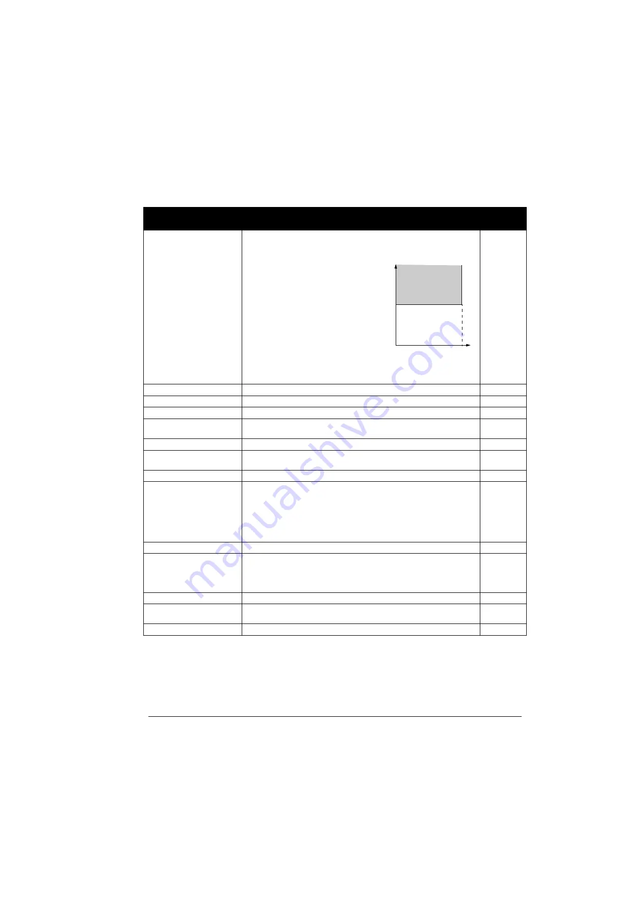
Selects how the drive reacts to a motor stall condition. The protection wakes
up if the drive has operated in a stall region (see figure below) longer than the
time set by parameter
STALL TIME.
NOT SEL
NOT SEL
Protection is inactive.
0
FAULT
The drive trips on fault MOTOR STALL and the motor coast to a stop.
1
ALARM
The drive generates alarm MOTOR STALL.
2
3011
STALL FREQUENCY
Defines the frequency limit for the stall function. See parameter
STALL
FUNCTION.
20
0.5…50.0 Hz
Frequency
1 = 0.1 Hz
3012
STALL TIME
Defines the time for the stall function. See parameter
STALL
FUNCTION.
20
10…400 s
Time
1 = 1 s
3013
UNDERLOAD FUNC
Selects how the drive reacts to underload. The protection wakes up if:
- the motor torque falls below the curve selected by parameter
UNDERLOAD CURVE,
- output frequency is higher than 10% of the nominal motor frequency and
- the above conditions have been valid longer than the time set by parameter
UNDERLOAD TIME.
NOT SEL
NOT SEL
Protection is inactive.
0
FAULT
The drive trips on fault UNDERLOAD and the motor coasts to a stop.
Note:
Set parameter value to FAULT only after the drive ID run is performed!
If FAULT is selected, the drive may generate an UNDERLOAD fault during ID
run.
1
ALARM
The drive generates alarm UNDERLOAD.
2
3014
UNDERLOAD TIME
Defines the time limit for the underload function. See parameter
UNDERLOAD FUNC.
20
10…400 s
Time limit
1 = 1 s
Parameters – complete descriptions
Index Name/Selection
Description
Def, FbEq
f
Torque
(%)
/
Par. 3011
Stall region
0.95 · user defined limit
With vector control
user defined limit =
2017 MAX TORQUE 1 /
2018 MAX TORQUE 2 /
(applies for positive and
negative torques)
With scalar control user
defined limit = 2003 MAX
CURRENT
Current
(A)
The control mode is selected by parameter
MOTOR CTRL MODE.
Summary of Contents for ACS350 Series
Page 1: ...ACS350 User s Manual ACS350 Drives 0 37 22 kW 0 5 30 HP ...
Page 4: ......
Page 8: ...Safety 8 ...
Page 18: ...Table of contents 18 ...
Page 24: ...Hardware description 24 ...
Page 44: ...Installation checklist 44 ...
Page 56: ...Start up control with I O and ID Run 56 ...
Page 140: ...Program features 140 ...
Page 242: ...Actual signals and parameters 242 ...
Page 266: ...Fieldbus control with embedded fieldbus 266 ...
Page 284: ...Fault tracing 284 ...
Page 288: ...Maintenance and hardware diagnostics 288 ...
Page 309: ...Dimensions 309 Frame size R2 IP20 NEMA 1 3AFE68586658 A Frame size R2 IP20 NEMA 1 VAR EMC ...
Page 311: ...Dimensions 311 Frame size R3 IP20 NEMA 1 3AFE68579872 B Frame size R3 IP20 NEMA 1 VAR EMC ...
Page 313: ......


