Actual signals and parameters
203
32 SUPERVISION
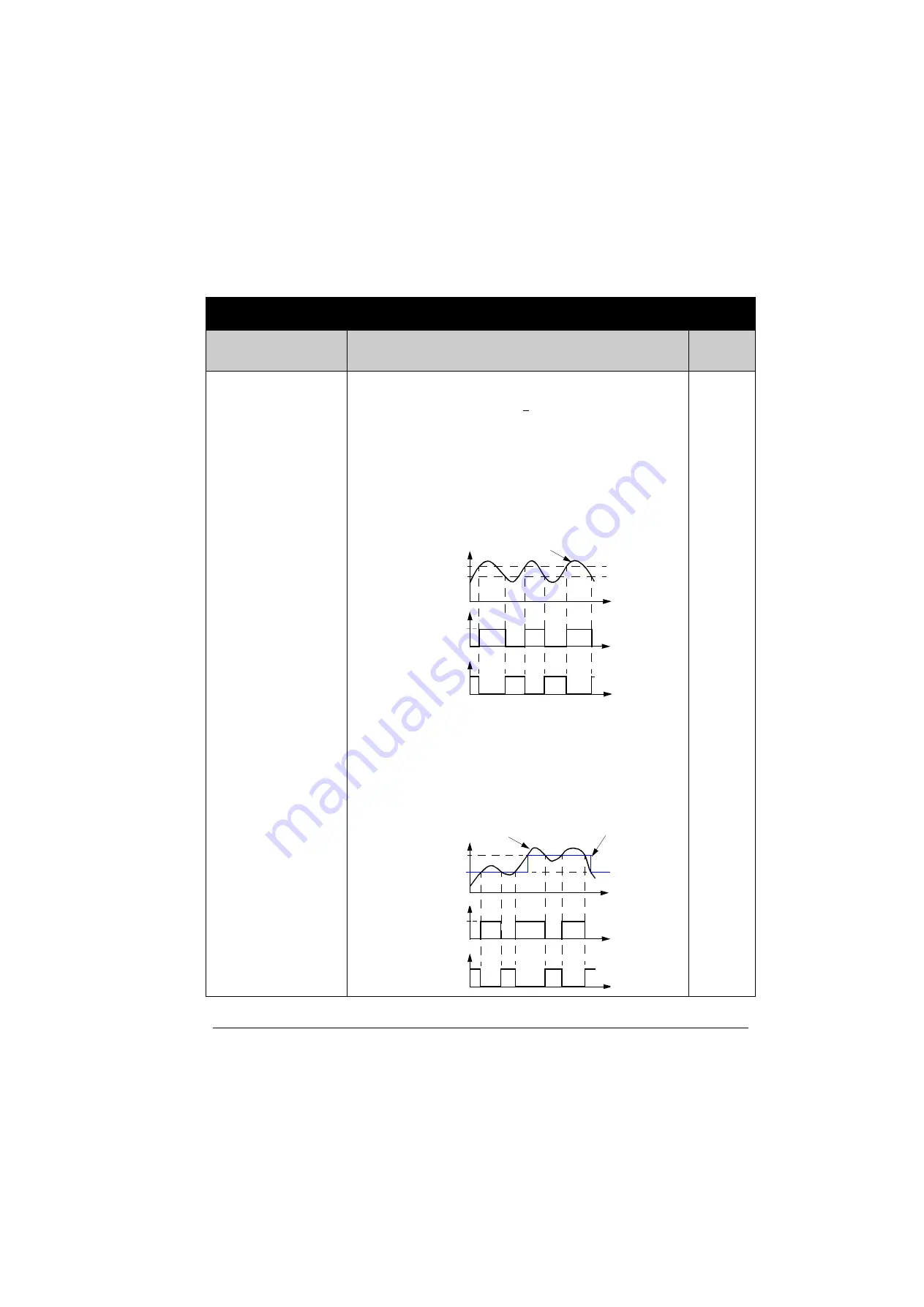
Signal supervision. Supervision status can be monitored with relay or
transistor output. See parameter groups
and
3201
SUPERV 1 PARAM
Selects the first supervised signal. Supervision limits are defined by
parameters
SUPERV 1 LIM LO and
SUPERV 1 LIM HI.
SUPERV 1 LIM LO <
SUPERV 1 LIM HI
Case A
=
RELAY OUTPUT 1 value is set to SUPRV1 OVER. Relay
energises when value of the signal selected with
SUPERV 1 PARAM
exceeds the supervision limit defined by
SUPERV 1 LIM HI. The relay
remains active until the supervised value drops below the low limit defined by
SUPERV 1 LIM LO.
Case B
=
RELAY OUTPUT 1 value is set to SUPRV 1 UNDER. Relay
energises when value of the signal selected with
SUPERV 1 PARAM
drops below the supervision limit defined by
SUPERV 1 LIM LO. The
relay remains active until the supervised value rises above the high limit
defined by
SUPERV 1 LIM HI.
SUPERV 1 LIM LO >
SUPERV 1 LIM HI
SUPERV 1 LIM HI remains active until the supervised
signal exceeds the higher limit
SUPERV 1 LIM LO, making it the active
limit. The new limit remains active until the supervised signal drops below the
lower limit
SUPERV 1 LIM HI, making it the active limit.
Case A
=
RELAY OUTPUT 1 value is set to SUPRV1 OVER. Relay is
energized whenever the supervised signal exceeds the active limit.
Case B
=
RELAY OUTPUT 1 value is set to SUPRV1 UNDER. Relay is
de-energized whenever the supervised signal drops below the active limit.
103
Parameters – complete descriptions
Index Name/Selection
Description
Def, FbEq
Value of supervised parameter
Case A
0
Energized (1)
0
HI (par. 3203)
t
t
t
LO (par. 3202)
Case B
Energized (1)
LO (par. 3202)
t
HI (par. 3203)
Value of supervised parameter
Case A
0
Energized (1)
0
t
t
Case B
Energized (1)
Active limit
Summary of Contents for ACS350 Series
Page 1: ...ACS350 User s Manual ACS350 Drives 0 37 22 kW 0 5 30 HP ...
Page 4: ......
Page 8: ...Safety 8 ...
Page 18: ...Table of contents 18 ...
Page 24: ...Hardware description 24 ...
Page 44: ...Installation checklist 44 ...
Page 56: ...Start up control with I O and ID Run 56 ...
Page 140: ...Program features 140 ...
Page 242: ...Actual signals and parameters 242 ...
Page 266: ...Fieldbus control with embedded fieldbus 266 ...
Page 284: ...Fault tracing 284 ...
Page 288: ...Maintenance and hardware diagnostics 288 ...
Page 309: ...Dimensions 309 Frame size R2 IP20 NEMA 1 3AFE68586658 A Frame size R2 IP20 NEMA 1 VAR EMC ...
Page 311: ...Dimensions 311 Frame size R3 IP20 NEMA 1 3AFE68579872 B Frame size R3 IP20 NEMA 1 VAR EMC ...
Page 313: ......


