408 Appendix: Resistor braking
Placing the brake resistor
Install all resistors in a place where they will cool.
WARNING!
The materials near the brake resistor must be non-flammable. The
surface temperature of the resistor is high. Air flowing from the resistor is of
hundreds of degrees Celsius. Protect the resistor against contact.
Protecting the system in brake circuit fault situations
Protecting the system in cable and brake resistor short-circuit situations
For short-circuit protection of the brake resistor connection, see
on page
. Alternatively, a two-conductor shielded cable with the same
cross-sectional area can be used.
Protecting the system in brake resistor overheating situations
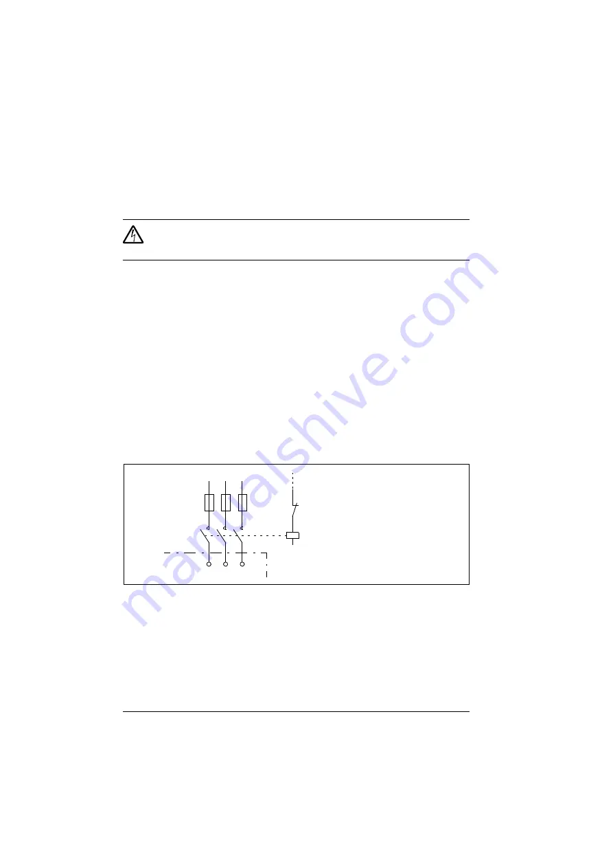
The following setup is essential for safety – it interrupts the main supply in fault
situations involving chopper shorts:
• Equip the drive with a main contactor.
• Wire the contactor so that it opens if the resistor thermal switch opens (an
overheated resistor opens the contactor).
Below is a simple wiring diagram example.
Electrical installation
For the brake resistor connections, see the power connection diagram of the drive on
page
.
U1 V1 W1
L1 L2 L3
1
2
3
4
5
6
K1
Q Thermal switch of the resistor
ACS355
Fuses
Summary of Contents for ACS355 series
Page 1: ...ABB machinery drives User s manual ACS355 drives ...
Page 4: ......
Page 16: ...16 ...
Page 32: ...32 Operation principle and hardware description ...
Page 58: ...58 Electrical installation ...
Page 74: ...74 Start up control with I O and ID run ...
Page 106: ...106 Control panels ...
Page 120: ...120 Application macros ...
Page 178: ...178 Program features ...
Page 338: ...338 Fieldbus control with embedded fieldbus ...
Page 368: ...368 Fault tracing ...
Page 404: ...404 Dimension drawings ...
Page 410: ...410 Appendix Resistor braking ...
Page 434: ...434 Appendix Permanent magnet synchronous motors PMSMs ...


