background image

24   Actual signals and parameters

0.0…1400.0 Hz Frequency

1 = 0.1 Hz

2615 USER 

DEFINED F3

Defines the third frequency point of the custom U/f curve.

25.0 Hz

0.0…1400.0 Hz Frequency

1 = 0.1 Hz

2617 USER 

DEFINED F4

Defines the fourth frequency point of the custom U/f curve. 40.0 Hz

0.0…1400.0 Hz Frequency

1 = 0.1 Hz

30 FAULT 

FUNCTIONS

Programmable protection functions

3029 FAULT RAMP 

STOP

Selects how the drive reacts when the drive trips to fault 
excepting Hardware critical faults (OVERCURRENT, DC 
OVERVOLT and SHORT CIRC), SAFE TORQUE OFF, 
STO1 LOST and STO2 LOST faults. 

1

DISABLE

 Drive makes coast stop when drive trips fault.

0

ENABLE

 Drive makes emergency ramp stop when drive trips fault 
using the emergency ramp stop deceleration time (par. 
22.08).

1

40 PROCESS PID 

SET 1

Process PID (PID1) control parameter set 1. 

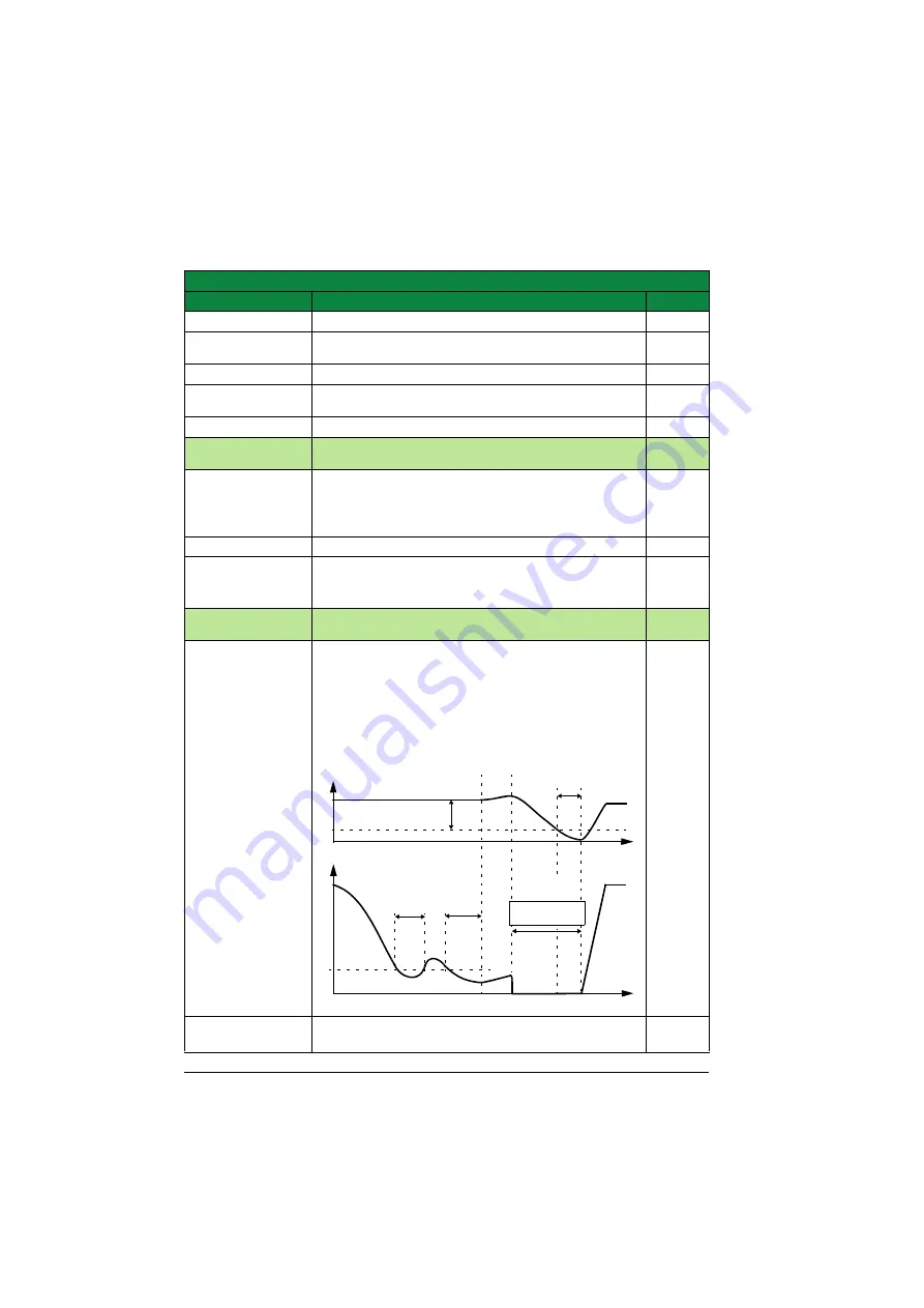
4023 PID SLEEP 

LEVEL

Defines the start limit for the sleep function. If the motor 
speed is below a set level (

4023

) longer than the sleep 

delay (4024), the drive shifts to the sleeping mode: The 
motor is stopped and the control panel shows alarm 
message PID SLEEP (2018).
Parameter 4022 SLEEP SELECTION must be set to 
INTERNAL.

0.0 Hz /
0 rpm

0.0…1400.0 Hz 
/ 0…32000 rpm

Sleep start level

1 = 0.1 Hz
1 rpm

All parameters
No.

Name/Value

Description

Def/FbEq

Wake-up level

deviation (

4025

)

<

 t

sd

PID output level 

PID process feedback

Stop

t

sd

 = Sleep delay 

(

4024

)

Sleep level 

(

4023

)

Start

Wake-up delay 

(

4026

)

t

sd

t

Control 

panel:

PID SLEEP

t

t

PID ref

Summary of Contents for ACS355 series

Page 1: ...ABB machinery drives Supplement ACS355 high speed program N826...

Page 2: ...er module user s manual 3AUA0000041017 FMBA 01 Modbus adapter module user s manual 3AFE68586704 FPBA 01 PROFIBUS DP adapter module user s manual 3AFE68573271 FRSA 00 RS 485 adapter board user s manual...

Page 3: ...Supplement ACS355 high speed program N826 Table of contents 3AXD50000017574 Rev A EN EFFECTIVE 2014 07 09 2014 ABB Oy All Rights Reserved...

Page 4: ......

Page 5: ...ive selection tables 11 Fault reaction for EM STOP 12 Settings 12 Fault reaction for Power loss 13 Settings 13 Smooth start ramp 13 Settings 13 Start enable 13 Settings 13 Fast user set change 14 Sett...

Page 6: ...2...

Page 7: ...nformation Safety Safety related instructions please refer to ACS355 user s manual 3AUA0000066143 English The safety instructions must be followed when installing operating and servicing the drive Ple...

Page 8: ...chnical data Appendixes Applicability The manual is applicable to the ACS355 high speed program firmware version 6303 or later See parameter 3301 FIRMWARE Option code N826 in the drive type code shows...

Page 9: ...also lists of related user settings in each section Actual signals and parameters page 15 describes the actual signals and parameters related to high speed program and gives the fieldbus equivalent v...

Page 10: ...10 Introduction to the supplement...

Page 11: ...r mode and up to 32000rpm in vector mode Drive selection tables Motor rated frequency range Hz Min switching frequency Recommend ed switching frequency Switching frequency control 2607 Minimum deratin...

Page 12: ...aults Drive makes an emergency ramp stop when fault occurs using the emergency ramp stop deceleration time par 22 08 Hardware critical faults OVERCURRENT DC OVERVOLT and SHORT CIRC will still make a c...

Page 13: ...1 when smooth start is not active Related parameters are listed in the table below Settings Start enable When start enable 1 or 2 is lost while drive is running then drive will make the stop set by p...

Page 14: ...ter 0186 changes to 0 when user set load starts and drive is ready to start when parameter 0186 changes to loaded user set value Related parameters are listed in the table below Settings Parameter Add...

Page 15: ...manual 3AUA0000066143 English Term Definition Actual signal Sequence program related signals measured or calculated by the drive Can be monitored by the user No user setting possible Def Parameter de...

Page 16: ...l signals and parameters Actual signals Actual signals No Name Value Description FbEq 01 OPERATING DATA Basic signals for monitoring the drive read only 0186 ACTIVE MACRO Shows which user macro is loa...

Page 17: ...REF1 Corresponds to the maximum setting of the used source signal E 50 0 Hz U 60 0 Hz 0 0 1400 0 Hz 0 32000 rpm Maximum value in rpm Hz if parameter 9904 MOTOR CTRL MODE setting is SCALAR FREQ See th...

Page 18: ...MIN FUNCTION and 3002 PANEL COMM ERR E 50 0 Hz U 60 0 Hz 0 0 1400 0 Hz 0 32000 rpm Speed in rpm Output frequency in Hz if parameter 9904 MOTOR CTRL MODE setting is SCALAR FREQ Constant speed 7 is used...

Page 19: ...er set selection through digital inputs DI1 DI2 and DI3 1 DI active 0 DI inactive 12 DI2 3 4 See selection DI1 2 3 13 DI3 4 5 See selection DI1 2 3 14 DI1 INV User parameter set control through invert...

Page 20: ...1 LOAD User set1 will be loaded 1 USER S2 LOAD User set2 will be loaded 2 USER S3 LOAD User set3 will be loaded 3 USER S4 LOAD User set4 will be loaded 4 USER S5 LOAD User set5 will be loaded 5 USER S...

Page 21: ...SPEED Defines the allowed minimum speed A positive or zero minimum speed value defines two ranges one positive and one negative A negative minimum speed value defines one speed range Note Rotation dir...

Page 22: ...1 and 2 Ramp pair 1 is defined by parameters 2202 2204 Ramp pair 2 is defined by parameters 2205 2207 DI5 NOT SEL Ramp pair 1 is used 0 DI1 Digital input DI1 1 ramp pair 2 0 ramp pair 1 1 DI2 See sel...

Page 23: ...0 1400 0 Hz 0 32000 rpm Limit in rpm Limit in Hz if parameter 9904 MOTOR CTRL MODE setting is SCALAR FREQ The value cannot be below the minimum parameter 2502 CRIT SPEED 1 LO 1 0 1 Hz 1 rpm 2504 CRIT...

Page 24: ...ault 0 ENABLE Drive makes emergency ramp stop when drive trips fault using the emergency ramp stop deceleration time par 22 08 1 40 PROCESS PID SET 1 Process PID PID1 control parameter set 1 4023 PID...

Page 25: ...rocess value eg pressure control by the drive running the pressure boost pump Measured pressure and the pressure reference are connected to the drive 6 TORQUE CTRL Torque control macro 8 AC500 MODBUS...

Page 26: ...t the saved parameter settings and the motor model are suitable for the application 8 USER S5 SAVE Save User 5 macro Stores the current parameter settings and the motor model 9 USER S6 LOAD User 6 mac...

Page 27: ...rmation on ABB product training navigate to www abb com drives and select Training courses Providing feedback on ABB Drives manuals Your comments on our manuals are welcome Go to www abb com drives an...

Page 28: ...www abb com drives www abb com drivespartners 3AXD50000017574 Rev A EN 2014 07 09 Contact us...

Reviews: