Program features 161
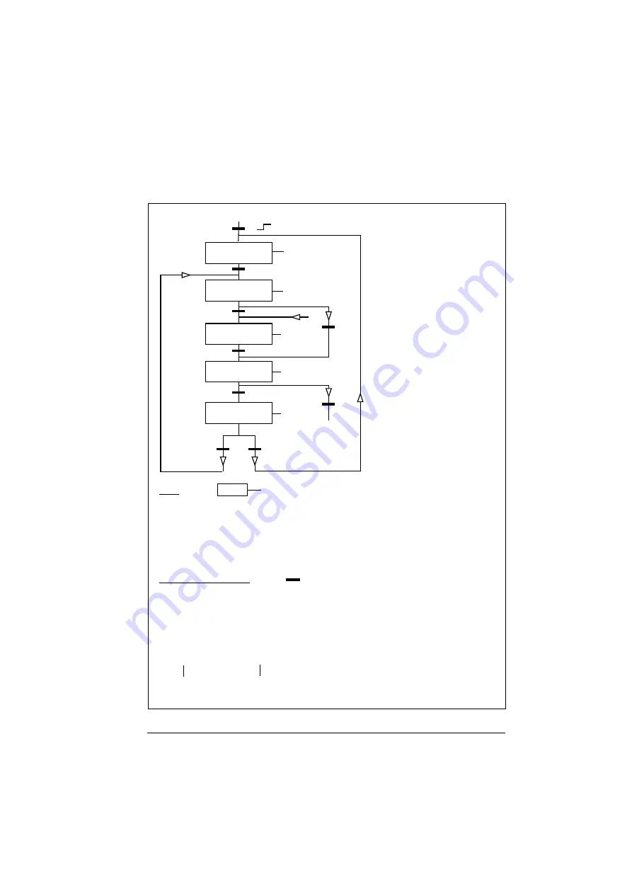
State shifts
1/1/1
0/1/1
1/1/0
1/1/0
1)
2)
3)
4)
7)
8)
5)
0/0/1
9)
6)
A
A
State (Symbol
)
- NN: State name
- X/Y/Z: State outputs/operations
X = 1 Open the brake. The relay output set to brake on/off control energizes.
Y = 1 Forced start. The function keeps the internal Start on until the brake is closed in
spite of the status of the external Start signal.
Z = 1
Ramp in zero. Forces the used speed reference (internal) to zero along a ramp.
NN
X/Y/Z
State change conditions (Symbol
)
1)
Brake control active 0 -> 1 OR Inverter is modulating = 0
2)
Motor magnetised = 1 AND Drive running = 1
3)
Brake is open AND Brake open delay passed AND Start = 1
4)
Start = 0
5)
Start = 0
6)
Start = 1
7)
Actual motor speed < Brake close speed AND Start = 0
8)
Start = 1
9)
Brake is closed AND Brake close delay passed = 1 AND Start = 0
RFG = Ramp function
generator in the speed control
loop (reference handling).
NO
MODULATION
RELEASE RFG
INPUT
OPEN
BRAKE
RFG INPUT
TO ZERO
CLOSE
BRAKE
From any state
(rising edge)
Summary of Contents for ACS355 series
Page 1: ...ABB machinery drives User s manual ACS355 drives ...
Page 4: ......
Page 16: ...16 ...
Page 32: ...32 Operation principle and hardware description ...
Page 58: ...58 Electrical installation ...
Page 74: ...74 Start up control with I O and ID run ...
Page 106: ...106 Control panels ...
Page 120: ...120 Application macros ...
Page 178: ...178 Program features ...
Page 338: ...338 Fieldbus control with embedded fieldbus ...
Page 368: ...368 Fault tracing ...
Page 404: ...404 Dimension drawings ...
Page 410: ...410 Appendix Resistor braking ...
Page 434: ...434 Appendix Permanent magnet synchronous motors PMSMs ...


