262 Actual signals and parameters
3305 PARAMETER
TABLE
Displays the version of the parameter table used in the
drive.
0000…FFFF
hex
For example, 400E hex
34 PANEL DISPLAY
Selection of actual signals to be displayed on the panel
3401 SIGNAL1
PARAM
Selects the first signal to be displayed on the control panel
in the Output mode.
103
0 = NOT
SELECTED
101…181
. For
example, 102 =
. If value is set to 0, no signal
is selected.
1 = 1
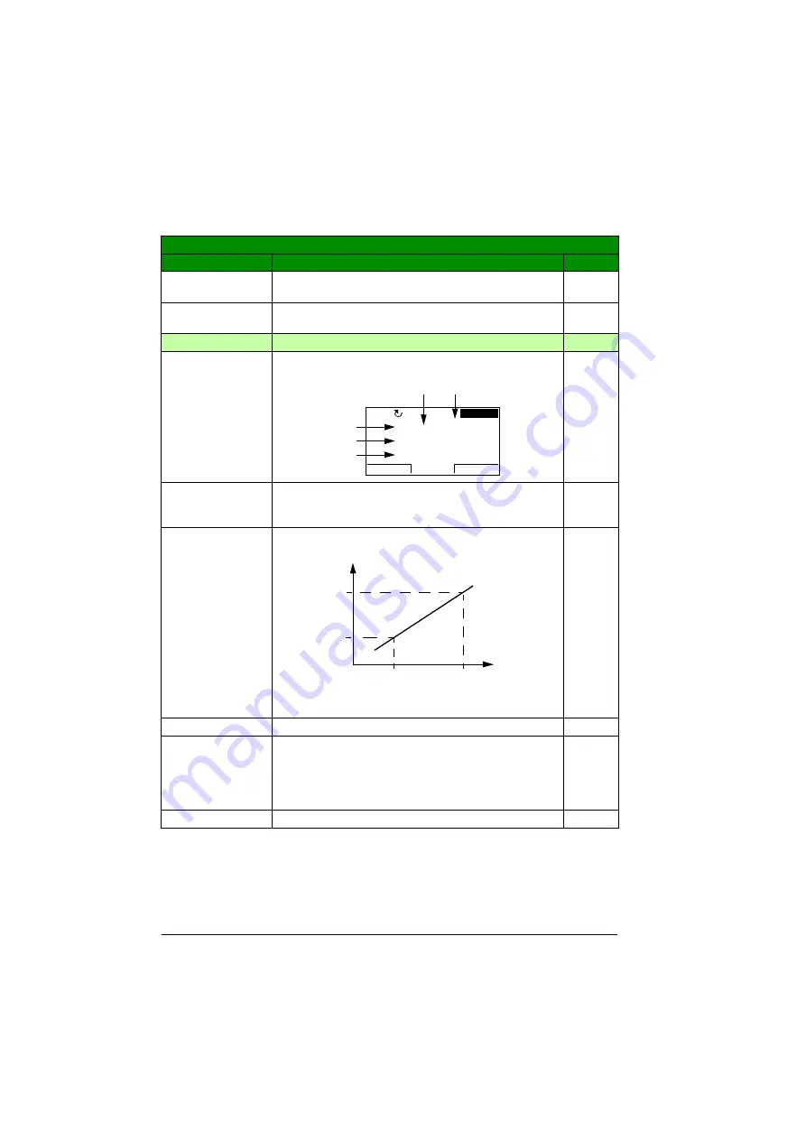
3402 SIGNAL1 MIN
Defines the minimum value for the signal selected by
parameter
Note:
Parameter is not effective if parameter
setting is
.
-
x…x
Setting range depends on parameter
setting.
-
3403 SIGNAL1 MAX Defines the maximum value for the signal selected by
parameter
. See the figure for
parameter
Note:
Parameter is not effective if parameter
setting is
.
-
x…x
Setting range depends on parameter
setting.
-
All parameters
No.
Name/Value
Description
Def/FbEq
Assistant control panel
DIR
MENU
00:00
LOC
15.0Hz
15 0 Hz
.
3 7 A
.
17 3 %
.
Source
value
Display
value
Summary of Contents for ACS355 series
Page 1: ...ABB machinery drives User s manual ACS355 drives ...
Page 4: ......
Page 16: ...16 ...
Page 32: ...32 Operation principle and hardware description ...
Page 58: ...58 Electrical installation ...
Page 74: ...74 Start up control with I O and ID run ...
Page 106: ...106 Control panels ...
Page 120: ...120 Application macros ...
Page 178: ...178 Program features ...
Page 338: ...338 Fieldbus control with embedded fieldbus ...
Page 368: ...368 Fault tracing ...
Page 404: ...404 Dimension drawings ...
Page 410: ...410 Appendix Resistor braking ...
Page 434: ...434 Appendix Permanent magnet synchronous motors PMSMs ...


