Actual signals and parameters 277
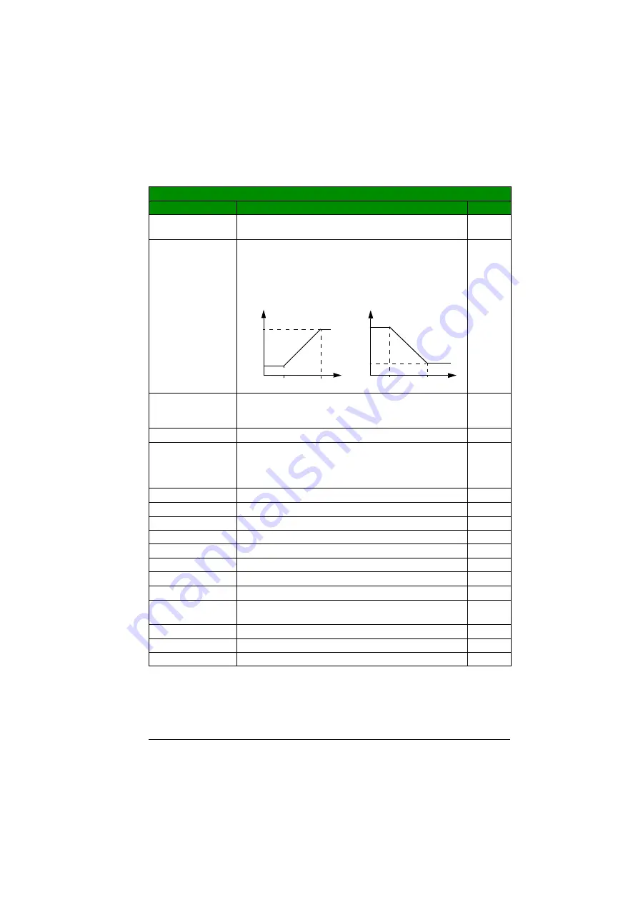
4012 SETPOINT
MIN
Defines the minimum value for the selected PID reference
signal source. See parameter
0.0%
-500.0…500.0% Value as a percentage.
Example:
Analog input AI1 is selected as the PID reference
). The reference
minimum and maximum correspond to the
and
settings as follows:
1 = 0.1%
4013 SETPOINT
MAX
Defines the maximum value for the selected PID reference
signal source. See parameters
and
100.0%
-500.0…500.0% Value as a percentage
1 = 0.1%
4014 FBK SEL
Selects the process actual value (feedback signal) for the
process PID controller: The sources for the variables ACT1
and ACT2 are further defined by parameters
and
.
ACT1
ACT1
1
ACT1-ACT2
Subtraction of ACT1 and ACT2
2
ACT1+ACT2
Addition of ACT1 and ACT2
3
ACT1*ACT2
Multiplication of ACT1 and ACT2
4
ACT1/ACT2
Division of ACT1 and ACT2
5
MIN(ACT1,2)
Selects the smaller of ACT1 and ACT2
6
MAX(ACT1,2)
Selects the higher of ACT1 and ACT2
7
sqrt(ACT1-2)
Square root of the subtraction of ACT1 and ACT2
8
sqA1+sqA2
Addition of the square root of ACT1 and the square root of
ACT2
9
sqrt(ACT1)
Square root of ACT1
10
COMM FBK 1
Signal
value
11
COMM FBK 2
Signal
value
12
All parameters
No.
Name/Value
Description
Def/FbEq
(MAX)
(MIN)
AI1
(%)
Ref
Ref
AI1
(%)
(MIN)
(MAX)
MAX > MIN
MIN > MAX
Summary of Contents for ACS355 series
Page 1: ...ABB machinery drives User s manual ACS355 drives ...
Page 4: ......
Page 16: ...16 ...
Page 32: ...32 Operation principle and hardware description ...
Page 58: ...58 Electrical installation ...
Page 74: ...74 Start up control with I O and ID run ...
Page 106: ...106 Control panels ...
Page 120: ...120 Application macros ...
Page 178: ...178 Program features ...
Page 338: ...338 Fieldbus control with embedded fieldbus ...
Page 368: ...368 Fault tracing ...
Page 404: ...404 Dimension drawings ...
Page 410: ...410 Appendix Resistor braking ...
Page 434: ...434 Appendix Permanent magnet synchronous motors PMSMs ...


