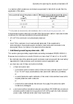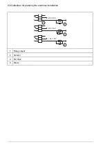
you connect the drive to the input power, examine the screws and do the necessary
actions shown in the table.
When to remove EMC screw or VAR screw
Screw material
Screw
label
IT systems (un-
grounded or high-
resistance groun-
ded) (C)
Corner-grounded
delta (B1), mid-
point-grounded
delta (B2) and
TT (D) systems
Symmetrically
grounded TN-S
systems, i.e, center-
grounded wye (A)
Remove
Remove
Do not remove
Metal
EMC
Do not remove
Do not remove
Do not remove
1)
Plastic
Remove
Do not remove
Do not remove
Metal
VAR
Do not remove
Do not remove
Do not remove
Plastic
A
B1
B2
A
C
D
L1
L2
L3
N
PE
L1
L2
L3
PE
L1
L2
L3
L1
L2
L3
N
PE
L1
L2
L3
PE
L1
L2
L3
N
1) Can install the metal screw included in the drive delivery to connect the internal EMC filter.
For the locations of the screws, refer to
Disconnecting the EMC filter or ground-to-phase
.
Electrical installation – IEC 67
Summary of Contents for ACS480-04-09A8-1
Page 1: ... ABB GENERAL PURPOSE DRIVES ACS480 drives Hardware manual ...
Page 2: ......
Page 4: ......
Page 14: ...14 ...
Page 22: ...22 ...
Page 28: ...28 ...
Page 38: ...38 ...
Page 44: ...44 ...
Page 118: ...118 ...
Page 126: ...126 ...
Page 174: ...174 ...
Page 176: ...Frame R0 Frame R0 front side IP20 UL open type 176 Dimension drawings ...
Page 177: ... Frame R0 bottom rear IP20 UL open type Dimension drawings 177 ...
Page 178: ...Frame R1 Frame R1 front side IP20 UL open type 178 Dimension drawings ...
Page 179: ... Frame R1 bottom rear IP20 UL open type Dimension drawings 179 ...
Page 180: ... Frame R1 front side UL Type 1 kit installed 180 Dimension drawings ...
Page 181: ... Frame R1 bottom rear UL Type 1 kit installed Dimension drawings 181 ...
Page 182: ...Frame R2 Frame R2 front side IP20 UL open type 182 Dimension drawings ...
Page 183: ... Frame R2 bottom rear IP20 UL open type Dimension drawings 183 ...
Page 184: ... Frame R2 front side UL Type 1 kit installed 184 Dimension drawings ...
Page 185: ... Frame R2 bottom rear UL Type 1 kit installed Dimension drawings 185 ...
Page 186: ...Frame R3 Frame R3 front side IP20 UL open type 186 Dimension drawings ...
Page 187: ... Frame R3 bottom rear IP20 UL open type Dimension drawings 187 ...
Page 188: ... Frame R3 front side UL Type 1 kit installed 188 Dimension drawings ...
Page 189: ... Frame R3 bottom rear UL Type 1 kit installed Dimension drawings 189 ...
Page 190: ...Frame R4 Frame R4 front side IP20 UL open type 190 Dimension drawings ...
Page 191: ... Frame R4 bottom rear IP20 UL open type Dimension drawings 191 ...
Page 192: ... Frame R4 front side UL Type 1 kit installed 192 Dimension drawings ...
Page 193: ... Frame R4 bottom rear UL Type 1 kit installed Dimension drawings 193 ...
Page 194: ...194 ...
Page 221: ... Declarations of conformity The Safe torque off function 221 ...
Page 231: ...Dimensions BIO 01 I O extension module 231 ...
Page 232: ...232 ...
Page 238: ...Dimensions 3AXD50000031148 rev A 238 BREL 01 relay output extension module ...

