■
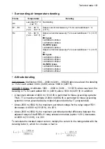
Surrounding air temperature derating
Derating
Temperature
Frame
No derating
Less than 50 °C
(122 °F)
All
Output current decreases by 1% for each additional 1 °C
(1.8 F).
50 … 60 °C
(122 … 140 °F)
R1…R3
Output current decreases by 1% for each additional 1 °C (1.8 F)
on:
IEC types
50 … 60 °C
(122 … 140 °F)
R4
•ACS480-04-033A-4
•ACS480-04-046A-4
UL (NEC) types
•ACS480-04-027A-4
Output current decreases by 2% for each additional 1 °C (1.8 F)
on:
IEC types
•ACS480-04-039A-4
•ACS480-04-050A-4
•ACS480-04-055A-2
UL (NEC) types
•ACS480-04-034A-4
•ACS480-04-042A-4
•ACS480-04-053A-2
■
Altitude derating
230 V drives: At altitudes 1000 … 2000 m (3281 … 6562 ft) above sea level, the derating
is 1% for each added 100 m (328 ft) above 1000 m (3281 ft).
400/480 V drives: At altitudes 1000 … 4000 m (3281 … 13123 ft) above sea level, the
derating is 1% for each added 100 m (328 ft) above 1000 m (3281 ft). In addition:
• A maximum altitude of 4000 m (13123 ft) is permitted for these grounding systems:
TN-S, TT. A maximum altitude of 2000 m (6562 ft) is permitted for these grounding
systems: corner-grounded delta, midpoint-grounded delta, IT (ungrounded).
• Above 2000 m (6562 ft), the maximum permitted voltage for the relay output RO1
decreases. At 4000 m (13123 ft), it is 30 V.
• Above 2000 m (6562 ft), the maximum permitted potential difference between the
adjacent relays of the BREL-01 relay extension module (L511) decreases.
At 4000 m (13123 ft), it is 30 V.
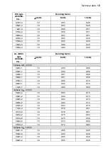
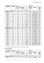
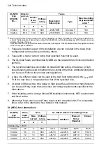
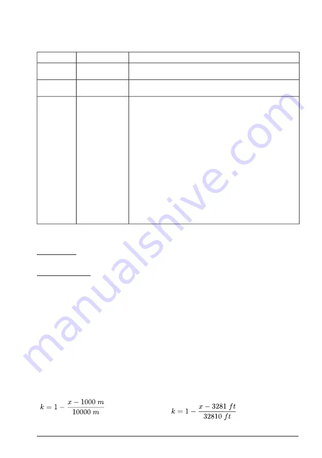
To calculate the derated output current, multiply the current in the ratings table with the
derating factor
k
, which for
x
meters or feet is:
Technical data 133
Summary of Contents for ACS480-04-09A8-1
Page 1: ... ABB GENERAL PURPOSE DRIVES ACS480 drives Hardware manual ...
Page 2: ......
Page 4: ......
Page 14: ...14 ...
Page 22: ...22 ...
Page 28: ...28 ...
Page 38: ...38 ...
Page 44: ...44 ...
Page 118: ...118 ...
Page 126: ...126 ...
Page 174: ...174 ...
Page 176: ...Frame R0 Frame R0 front side IP20 UL open type 176 Dimension drawings ...
Page 177: ... Frame R0 bottom rear IP20 UL open type Dimension drawings 177 ...
Page 178: ...Frame R1 Frame R1 front side IP20 UL open type 178 Dimension drawings ...
Page 179: ... Frame R1 bottom rear IP20 UL open type Dimension drawings 179 ...
Page 180: ... Frame R1 front side UL Type 1 kit installed 180 Dimension drawings ...
Page 181: ... Frame R1 bottom rear UL Type 1 kit installed Dimension drawings 181 ...
Page 182: ...Frame R2 Frame R2 front side IP20 UL open type 182 Dimension drawings ...
Page 183: ... Frame R2 bottom rear IP20 UL open type Dimension drawings 183 ...
Page 184: ... Frame R2 front side UL Type 1 kit installed 184 Dimension drawings ...
Page 185: ... Frame R2 bottom rear UL Type 1 kit installed Dimension drawings 185 ...
Page 186: ...Frame R3 Frame R3 front side IP20 UL open type 186 Dimension drawings ...
Page 187: ... Frame R3 bottom rear IP20 UL open type Dimension drawings 187 ...
Page 188: ... Frame R3 front side UL Type 1 kit installed 188 Dimension drawings ...
Page 189: ... Frame R3 bottom rear UL Type 1 kit installed Dimension drawings 189 ...
Page 190: ...Frame R4 Frame R4 front side IP20 UL open type 190 Dimension drawings ...
Page 191: ... Frame R4 bottom rear IP20 UL open type Dimension drawings 191 ...
Page 192: ... Frame R4 front side UL Type 1 kit installed 192 Dimension drawings ...
Page 193: ... Frame R4 bottom rear UL Type 1 kit installed Dimension drawings 193 ...
Page 194: ...194 ...
Page 221: ... Declarations of conformity The Safe torque off function 221 ...
Page 231: ...Dimensions BIO 01 I O extension module 231 ...
Page 232: ...232 ...
Page 238: ...Dimensions 3AXD50000031148 rev A 238 BREL 01 relay output extension module ...


