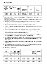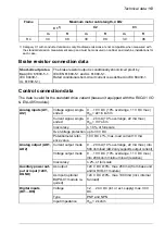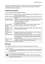
Frame
size
Noise
Air flow
Typical power loss
1)
UL (NEC)
type
ACS480-04-
dB(A)
CFM
m3/h
BTU/h
W
R1
63
33
57
229
67
04A6-1
R1
63
33
57
317
93
06A6-1
R1
63
33
57
362
106
07A4-1
R2
59
37
63
314
92
09A3-1
R2
59
37
63
392
115
11A6-1
3-phase
U
N = 230 V
R1
63
33
57
133
39
02A3-2
R1
63
33
57
194
57
03A5-2
R1
63
33
57
246
72
04A6-2
R1
63
33
57
379
111
06A6-2
R1
63
33
57
358
105
07A5-2
R2
59
37
63
508
149
11A6-2
R3
66
75
128
904
265
017A-2
R3
66
75
128
1358
398
024A-2
R4
69
88
150
1194
350
031A-2
R4
69
88
150
1914
561
046A-2
R4
69
88
150
2307
676
053A-2
3-phase
U
N = 480 V
R1
63
33
57
150
44
02A1-4
R1
63
33
57
188
55
03A0-4
R1
63
33
57
212
62
03A5-4
R1
63
33
57
311
91
04A8-4
R1
63
33
57
341
100
06A0-4
R1
63
33
57
478
140
07A6-4
R2
59
37
63
563
165
011A-4
R3
66
75
128
884
259
014A-4
R3
66
75
128
1331
390
021A-4
R4
69
88
150
1351
396
027A-4
R4
69
88
150
1696
497
034A-4
R4
69
88
150
2293
672
042A-4
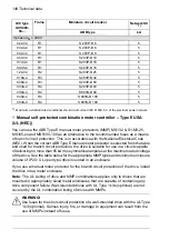
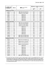
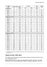
1) Typical drive losses when it operates at 90% of the motor nominal frequency and 100% of the drive nominal
output current.
Typical power cable sizes
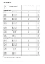
The tables in this section give the typical power cable and conductor sizes for use at
the nominal drive current.
Note:
IEC/EN 61800-5-1 requires two separate PE (ground) conductors for a fixed
connection, if the cross-sectional area of the PE conductor is less than 10 mm
2
Cu.
Technical data 153
Summary of Contents for ACS480-04-09A8-1
Page 1: ... ABB GENERAL PURPOSE DRIVES ACS480 drives Hardware manual ...
Page 2: ......
Page 4: ......
Page 14: ...14 ...
Page 22: ...22 ...
Page 28: ...28 ...
Page 38: ...38 ...
Page 44: ...44 ...
Page 118: ...118 ...
Page 126: ...126 ...
Page 174: ...174 ...
Page 176: ...Frame R0 Frame R0 front side IP20 UL open type 176 Dimension drawings ...
Page 177: ... Frame R0 bottom rear IP20 UL open type Dimension drawings 177 ...
Page 178: ...Frame R1 Frame R1 front side IP20 UL open type 178 Dimension drawings ...
Page 179: ... Frame R1 bottom rear IP20 UL open type Dimension drawings 179 ...
Page 180: ... Frame R1 front side UL Type 1 kit installed 180 Dimension drawings ...
Page 181: ... Frame R1 bottom rear UL Type 1 kit installed Dimension drawings 181 ...
Page 182: ...Frame R2 Frame R2 front side IP20 UL open type 182 Dimension drawings ...
Page 183: ... Frame R2 bottom rear IP20 UL open type Dimension drawings 183 ...
Page 184: ... Frame R2 front side UL Type 1 kit installed 184 Dimension drawings ...
Page 185: ... Frame R2 bottom rear UL Type 1 kit installed Dimension drawings 185 ...
Page 186: ...Frame R3 Frame R3 front side IP20 UL open type 186 Dimension drawings ...
Page 187: ... Frame R3 bottom rear IP20 UL open type Dimension drawings 187 ...
Page 188: ... Frame R3 front side UL Type 1 kit installed 188 Dimension drawings ...
Page 189: ... Frame R3 bottom rear UL Type 1 kit installed Dimension drawings 189 ...
Page 190: ...Frame R4 Frame R4 front side IP20 UL open type 190 Dimension drawings ...
Page 191: ... Frame R4 bottom rear IP20 UL open type Dimension drawings 191 ...
Page 192: ... Frame R4 front side UL Type 1 kit installed 192 Dimension drawings ...
Page 193: ... Frame R4 bottom rear UL Type 1 kit installed Dimension drawings 193 ...
Page 194: ...194 ...
Page 221: ... Declarations of conformity The Safe torque off function 221 ...
Page 231: ...Dimensions BIO 01 I O extension module 231 ...
Page 232: ...232 ...
Page 238: ...Dimensions 3AXD50000031148 rev A 238 BREL 01 relay output extension module ...


