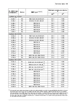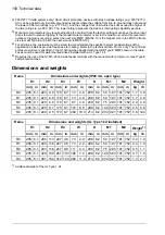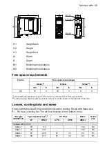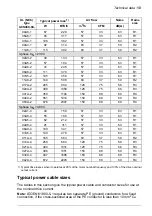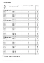
Maximum motor cable length, 4 kHz
Frame
C3
C2
C1
1)
ft
m
ft
m
ft
m
98
30
98
30
98
30
R4
1) Category C1 with conducted emissions only. Radiated emissions are not compatible when measured with
the standard emission measurement setup and must be measured on cabinet and machine installations for
each case.
Brake resistor connection data
The brake resistor output is conditionally short-circuit proof by
IEC/EN 61800-5-1 and UL 61800-5-1.
Short-circuit protec-
tion
(IEC 61800-5-1,
IEC 60439-1,
UL 61800-5-1)
Rated conditional short-circuit current is as defined in IEC 60439-1.
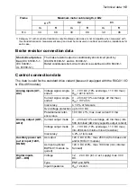
Control connection data
The data is valid for the standard drive variant (base unit equipped with the RIIO-01 I/O
& EIA-485 module).
0 … 10 V DC (10% overrange, 11 V DC max.)
Voltage signal, single-
ended
Analog inputs (AI1,
AI2)
R
in = 221.6 kohm
0 … 20 mA (10% overrange, 22 mA max.)
Current signal, single-
ended
R
in = 137 ohm
≤ 1.0%, of full scale
Inaccuracy
up to 30 V DC
Overvoltage protection
10 V DC ±1%, max. load current 10 mA
Potentiometer refer-
ence value
0 … 20 mA (10% overrange, 22 mA max.) into
500 ohm load (AO2 only supports output current)
Current output mode
Analog output (AO1,
AO2)
0 … 10 V DC (10% overrange, 11 V DC max.)
into 200 kohm minimum load (resistive)
Voltage output mode
≤ 2%, of full scale
Inaccuracy
+24 V DC ±10%, max. 250 mA (from base unit
and/or RIIO-01 module)
As output
Auxiliary power out-
put or input (+24V,
DGND)
+24 V DC ±10%, max. 1000 mA (incl. internal
fan load)
As input (optional
BAPO-01 module re-
quired)
12 … 24 V DC (int. or ext. supply) max. 30 V
DC.
Voltage
Digital inputs
(DI1…DI6)
PNP and NPN
Type
R
in = 2 kohm
Input impedance
Technical data 163
Summary of Contents for ACS480-04-09A8-1
Page 1: ... ABB GENERAL PURPOSE DRIVES ACS480 drives Hardware manual ...
Page 2: ......
Page 4: ......
Page 14: ...14 ...
Page 22: ...22 ...
Page 28: ...28 ...
Page 38: ...38 ...
Page 44: ...44 ...
Page 118: ...118 ...
Page 126: ...126 ...
Page 174: ...174 ...
Page 176: ...Frame R0 Frame R0 front side IP20 UL open type 176 Dimension drawings ...
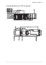
Page 177: ... Frame R0 bottom rear IP20 UL open type Dimension drawings 177 ...
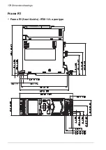
Page 178: ...Frame R1 Frame R1 front side IP20 UL open type 178 Dimension drawings ...
Page 179: ... Frame R1 bottom rear IP20 UL open type Dimension drawings 179 ...
Page 180: ... Frame R1 front side UL Type 1 kit installed 180 Dimension drawings ...
Page 181: ... Frame R1 bottom rear UL Type 1 kit installed Dimension drawings 181 ...
Page 182: ...Frame R2 Frame R2 front side IP20 UL open type 182 Dimension drawings ...
Page 183: ... Frame R2 bottom rear IP20 UL open type Dimension drawings 183 ...
Page 184: ... Frame R2 front side UL Type 1 kit installed 184 Dimension drawings ...
Page 185: ... Frame R2 bottom rear UL Type 1 kit installed Dimension drawings 185 ...
Page 186: ...Frame R3 Frame R3 front side IP20 UL open type 186 Dimension drawings ...
Page 187: ... Frame R3 bottom rear IP20 UL open type Dimension drawings 187 ...
Page 188: ... Frame R3 front side UL Type 1 kit installed 188 Dimension drawings ...
Page 189: ... Frame R3 bottom rear UL Type 1 kit installed Dimension drawings 189 ...
Page 190: ...Frame R4 Frame R4 front side IP20 UL open type 190 Dimension drawings ...
Page 191: ... Frame R4 bottom rear IP20 UL open type Dimension drawings 191 ...
Page 192: ... Frame R4 front side UL Type 1 kit installed 192 Dimension drawings ...
Page 193: ... Frame R4 bottom rear UL Type 1 kit installed Dimension drawings 193 ...
Page 194: ...194 ...
Page 221: ... Declarations of conformity The Safe torque off function 221 ...
Page 231: ...Dimensions BIO 01 I O extension module 231 ...
Page 232: ...232 ...
Page 238: ...Dimensions 3AXD50000031148 rev A 238 BREL 01 relay output extension module ...

