ACS51
0
User’s Manual
11
Installation
Installing the Drive
Warning!
Before installing the ACS510, ensure the input power supply to the drive is
off.
Prepare the Mounting Location
The ACS510 should only be mounted where all of the
requirements defined in "Preparing for Installation" on
page 8 are met.
1. Mark the position of the mounting holes.
2. Drill the holes.
Note!
Frame sizes R3 and R4 have four holes along the top. Use only two. If
possible, use the two outside holes (to allow room to remove the fan for
maintenance).
Note!
ACS400 drives can be replaced using the original mounting holes. For R1 and
R2 frame sizes, the mounting holes are identical. For R3 and R4 frame sizes, the
inside mounting holes on the top of ACS510 drives match ACS400 mounts.
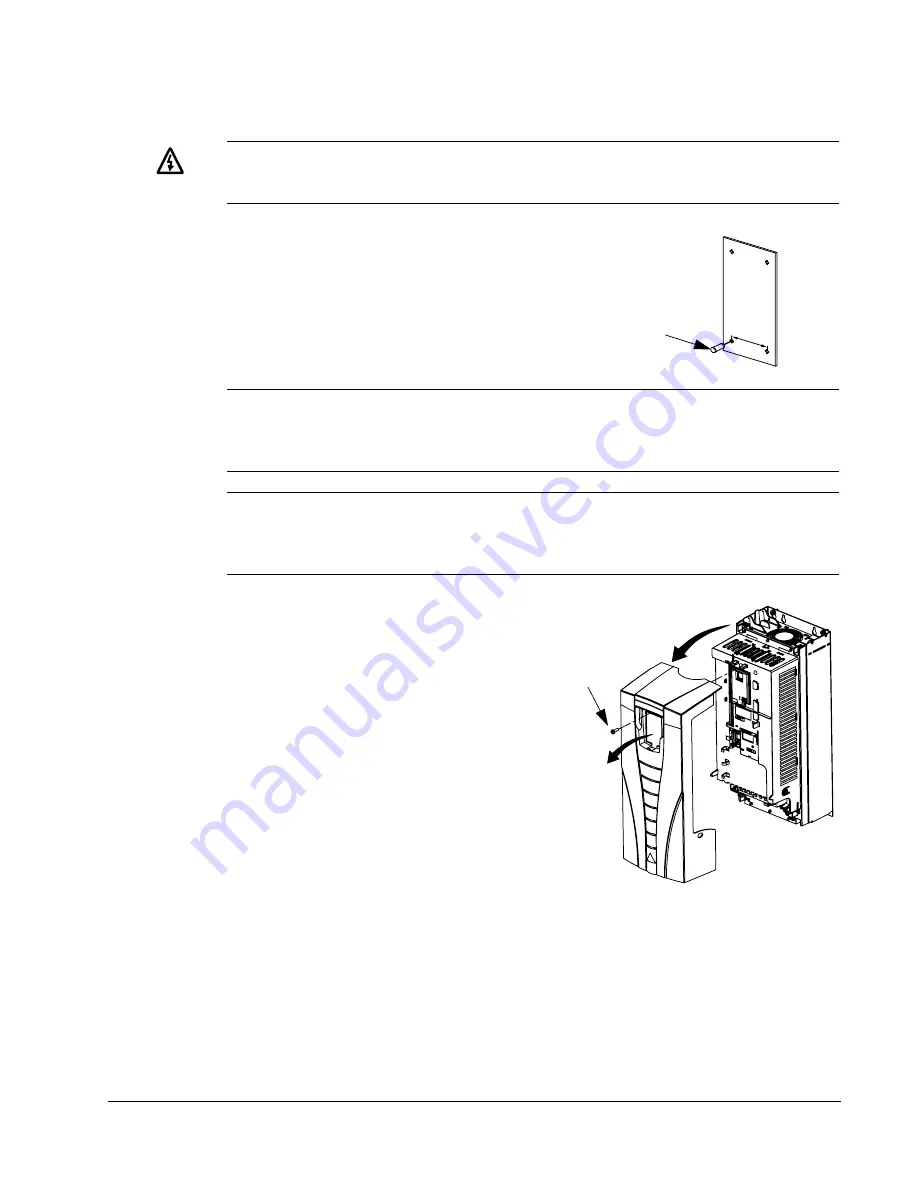
Remove Front Cover
IP21
1. Remove the control panel, if attached.
2. Loosen the captive screw at the top.
3. Pull near the top to remove the cover.
X0002
1
3
IP2000
1
2
Supplied from China by: Guangzhou Tofee Electro Mechanical Equipment Co., Ltd
Email: info@tofee.com.cn


