ACS510 User’s Manual
227
Technical Data
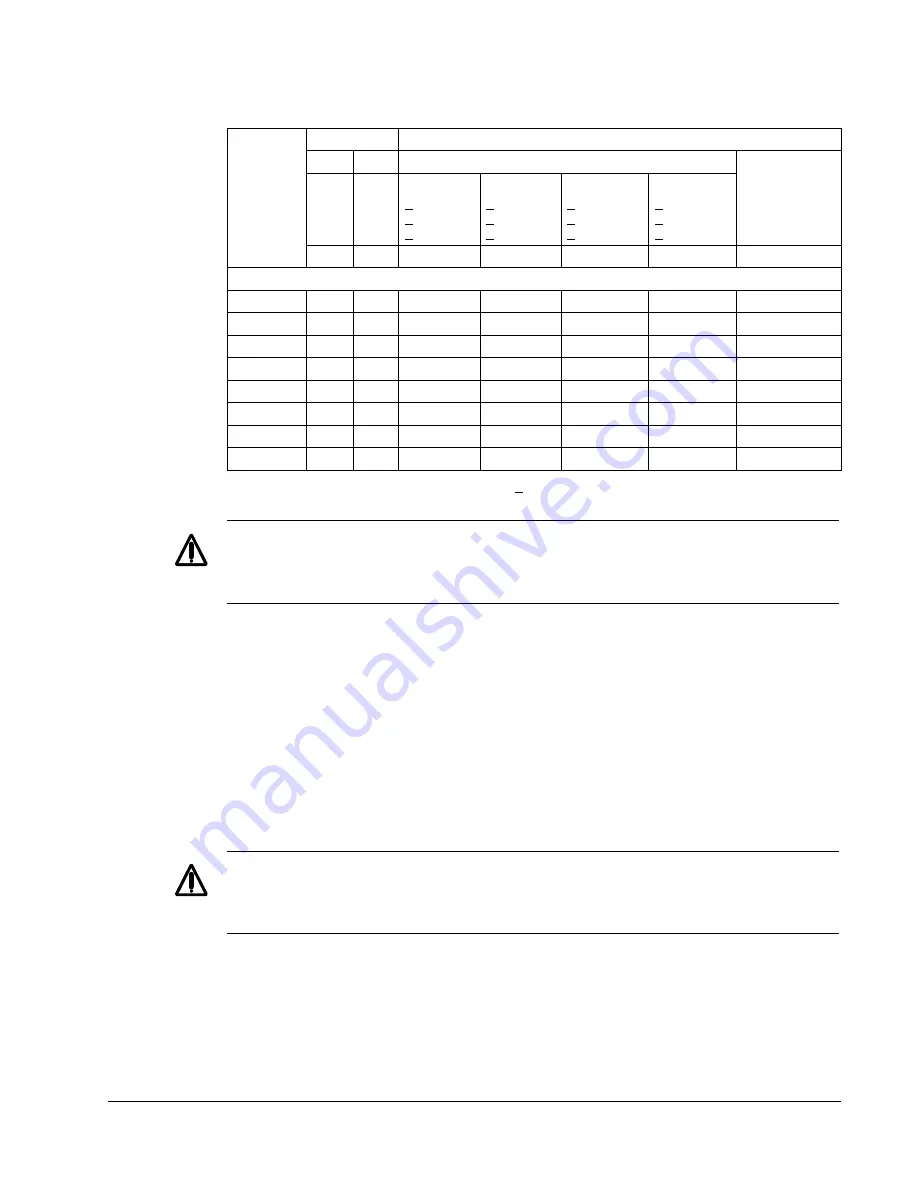
380…480 V Drives
1. Resistor time constant specification must be > 85 seconds.
WARNING!
Never use a brake resistor with a resistance below the minimum value
specified for the particular drive. The drive and the internal chopper are not able to
handle the overcurrent caused by the low resistance.
Symbols
R
MIN
–
Minimum allowed braking resistor.
R
MAX
–
Maximum resistance allowed if maximum braking torque is necessary.
P
rx
–
Duty-cycle based resistor power rating in deceleration braking, where “x” is
ON
MAX
time.
Installing and Wiring Resistors
All resistors must be installed outside the drive module in a place where they can
dissipate heat.
Warning!
The surface temperature of the resistor is very high and air flowing from
the resistor is very hot. Materials near the brake resistor must be non-flammable.
Provide protection from accidental contact with the resistor.
To ensure that the input fuses protect the resistor cable, use resistor cables with the
same rating as used for the power input to the drive.
The maximum length of the resistor cable(s) is 10 m (33 ft). See the "Power
Connection Diagrams" on page 15 for the resistor cable connection points.
Type Code
ACS510-
01-
see below
Resistance
Resistor
1
Minimum Continuous Power Rating
Deceleration-to-Zero Rating
P
rcont
Continuous ON
> 60 s ON
> 25% Duty
R
MAX
R
MIN
P
r3
< 3 s ON
> 27 s OFF
< 10% Duty
P
r10
< 10 s ON
> 50 s OFF
< 17% Duty
P
r30
< 30 s ON
> 180 s OFF
< 14% Duty
P
r60
< 60 s ON
> 180 s OFF
< 25% Duty
ohm
ohm
W
W
W
W
W
Three-phase supply voltage,
380
…
480 V
-03A3-4
641
120
65
120
175
285
1100
-04A1-4
470
120
90
160
235
390
1500
-05A6-4
320
120
125
235
345
570
2200
-07A2-4
235
80
170
320
470
775
3000
-09A4-4
192
80
210
400
575
950
4000
-012A-4
128
80
315
590
860
1425
5500
-017A-4
94
63
425
800
1175
1950
7500
-025A-4
64
63
625
1175
1725
2850
11000
Supplied from China by: Guangzhou Tofee Electro Mechanical Equipment Co., Ltd
Email: info@tofee.com.cn


