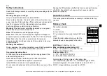
EN
21
Status indications and fault tracing
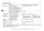
(*) Automatically reset if the AUTORESET is ON. See
on page
.
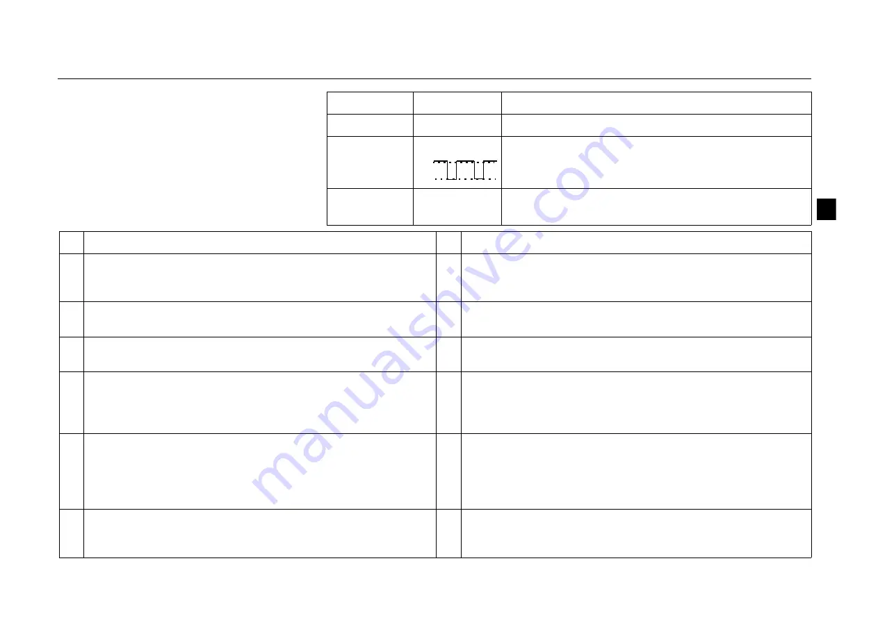
ACS55 has two status indication LEDs, visible
through the front cover.
If the drive detects a problem, the red LED will
blink. After fixing the problem, reset by
switching the start signal off. If start is off
already, turn it first on and then off again.
See the table below for the fault codes (= the
number of LED blinks).
Green LED
Red LED
Description
On
Off
ACS55 operates normally.
On
Blinking
Protective function has been activated. Number of
blinks indicates the fault code.
Blinking
Blinking
ACS55 will reset automatically within 3 seconds. (*)
Warning!
Motor starts, if start signal is on.
#
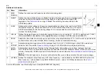
Possible causes and what to do
#
Possible causes and what to do
1
DC overvoltage (*). 1) Mains voltage is too high: Check supply.
2) Deceleration ramp time is too short compared to the load inertia:
Increase ACC/DEC time with potentiometer.
7
Motor overload (
I
2
t
overload): 1) Check the load, and verify that
the motor size is suitable for ACS55. 2) Verify that setting of
MOTOR I NOM potentiometer is correct.
2
DC undervoltage (*). Mains voltage is too low: Check supply.
8
Inverter overload or excessive internal temperature: 1) Load is too
high or 2) drive cooling is insufficient.
3
Output short circuit: Switch off the power and check the motor
windings and motor cable.
9
Other fault. Internal error. Turn power off and on again. If problem
persists, replace the unit.
4
Output overcurrent. 1) Acceleration time is too short compared to
the load inertia: Increase ACC/DEC time with potentiometer. 2)
Motor and drive sizes do not match: Check motor.
10 Parameterization fault.
Note:
Both LEDs will blink. DIP switches
have been moved from default setting after the drive has been
parameterized with DriveConfig tool. Put the switches back to
default position.
5
Reserved
11 Drive is battery-powered. Drive status indicates Fault, because it is
not possible to start the drive. For drive operation, the drive must
be connected to mains. However, when the drive is powered from
the DriveConfig kit supply, the connection between DriveConfig
and the drive is OK.
6
Analogue input value is less than 4 mA/2 V. (*)
Note:
This
supervision is active if AI OFFSET is ON.
12 Drive has been controlled by DriveConfig (or other application via
serial communication) and the communication has been lost.
Check the communication.
On
Off
1
2
GHV Vertriebs-GmbH • 85567 Grafing • Tel: +49 (0) 8092 8189 0 • Fax: +49 (0) 8092 8189 99 • info@ghv.de • www.ghv.de

