ACS550-02/U2 User’s Manual
65
Start-up, control with I/O and ID Run
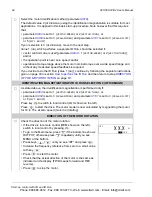
To change the direction of the motor rotation:
• Disconnect input power from the drive, and wait 5 minutes
for the intermediate circuit capacitors to discharge. Measure
the voltage between each input terminal (U1, V1 and W1)
and earth with a multimeter to ensure that the drive is
discharged.
• Exchange the position of two motor cable phase conductors
at the drive output terminals or at the motor connection box.
• Verify your work by applying input power and repeating the
check as described above.
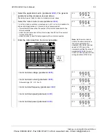
SPEED LIMITS AND ACCELERATION/DECELERATION TIMES
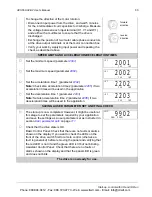
Set the minimum speed (parameter
2001
).
Set the maximum speed (parameter
2002
).
Set the acceleration time 1 (parameter
2202
).
Note:
Check also acceleration time 2 (parameter
2205
) if two
acceleration times will be used in the application.
Set the deceleration time 1 (parameter
2203
).
Note:
Set also deceleration time 2 (parameter
2206
) if two
deceleration times will be used in the application.
SAVING A USER PARAMETER SET AND FINAL CHECK
The start-up is now completed. However, it might be useful at
this stage to set the parameters required by your application
and save the settings as a user parameter set as instructed in
section
User parameter sets
on page
111
.
Check that the drive state is OK.
Basic Control Panel: Check that there are no faults or alarms
shown on the display. If you want to check the LEDs on the
front of the drive, switch first to remote control (otherwise a
fault is generated) before removing the panel and verifying that
the red LED is not lit and the green LED is lit but not blinking.
Assistant Control Panel: Check that there are no faults or
alarms shown on the display and that the panel LED is green
and does not blink.
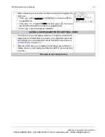
The drive is now ready for use.
forward
direction
reverse
direction
LOC
PAR FWD
2001
LOC
PAR FWD
2002
LOC
PAR FWD
2202
LOC
PAR FWD
2203
LOC
PAR FWD
9902
Phone: 800.894.0412 - Fax: 888.723.4773 - Web: www.clrwtr.com - Email: info@clrwtr.com

