background image

ABB general purpose drives

Hardware manual

ACS580-01 drives (0.75 to 250 kW)


Summary of Contents for ACS580-01 drives

Page 1: ...ABB general purpose drives Hardware manual ACS580 01 drives 0 75 to 250 kW...

Page 2: ...for ACS AP control panel 3AUA0000100140 DPMP 02 03 mounting platform for ACS AP control panel 3AUA0000136205 FCAN 01 CANopen adapter module user s manual 3AFE68615500 FCNA 01 ControlNet adapter module...

Page 3: ...manual ACS580 01 drives 0 75 to 250 kW 3AXD50000018826 Rev D EN EFFECTIVE 2015 11 02 2015 ABB Oy All Rights Reserved 1 Safety instructions Table of contents 4 Mechanical installation 6 Electrical inst...

Page 4: ......

Page 5: ...apter 21 Applicability 21 Target audience 21 Purpose of the manual 21 Contents of this manual 22 Related documents 22 Categorization by frame size 23 Quick installation and commissioning flowchart 24...

Page 6: ...ypes 60 Motor cable shield 61 Additional US requirements 61 Selecting the control cables 62 Shielding 62 Signals in separate cables 62 Signals allowed to be run in the same cable 62 Relay cable 63 Con...

Page 7: ...Connecting the power cables 80 Connection diagram 80 Connection procedure frames R0 R4 81 Connection procedure frame R5 88 Connection procedure frames R6 R9 92 Motor cable 93 DC connection 96 Connect...

Page 8: ...7 Ambient temperature derating IP55 138 IP55 UL Type 12 drive type 045A 4 138 IP55 UL Type 12 drive type 293A 4 138 IP55 UL Type 12 drive type 363A 4 139 IP55 UL Type 12 drive type 430A 4 139 Switchin...

Page 9: ...gs Contents of this chapter 167 Frame R0 IP21 168 Frame R0 IP55 169 Frame R1 IP21 170 Frame R1 IP55 171 Frame R2 IP21 172 Frame R2 IP55 173 Frame R3 IP21 174 Frame R3 IP55 175 Frame R4 IP21 176 Frame...

Page 10: ...tracing 205 Safety data 206 Abbreviations 208 Declaration of conformity 208 Certificate 208 13 Optional I O extension modules What this chapter contains 209 CMOD 01 multifunction extension module ext...

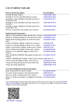
Page 11: ...Table of contents 11 Document library on the Internet 225...

Page 12: ...12 Table of contents...

Page 13: ...h or damage to the equipment They also tell you how to prevent the danger Notes draw attention to a particular condition or fact or give information on a subject The manual uses these warning symbols...

Page 14: ...of the electrical supply Keep the drive in its package or protect it otherwise from dust and burr from drilling and grinding until you install it Protect also the installed drive against dust and burr...

Page 15: ...ty circuits see the instructions provided with them Note If you select an external source for start command and it is on and the start command is level triggered the drive will start immediately after...

Page 16: ...and attach a warning notice to it Disconnect any external power sources from the control circuits before you do work on the control cables After you disconnect the drive always wait for 5 minutes to l...

Page 17: ...r capacitors This will damage the drive See page 77 Note Disconnecting the internal EMC filter increases the conducted emission and reduces the drive EMC compatibility considerably See section EMC com...

Page 18: ...to the protective earth PE bus of the power supply Make sure that the conductivity of the protective earth PE conductors is sufficient See section Selecting the power cables on page 58 Obey the local...

Page 19: ...e during work Make sure that no other system like hydraulic crawling drives can rotate the motor directly or through any mechanical connection like felt nip rope etc Measure that the installation is d...

Page 20: ...drive Give a stop command to the drive before you reset a fault If you have an external source for the start command and the start is on the drive will start immediately after the fault reset unless...

Page 21: ...missioning the drive The flowchart refers to chapters sections in this manual Applicability The manual applies to the ACS580 01 drives Target audience The reader is expected to know the fundamentals o...

Page 22: ...the assembly and the compatibility with IT ungrounded and corner grounded TN systems It then shows how to connect the power and control cables install optional modules and connect a PC Installation c...

Page 23: ...anufactured in frames frame sizes R0 R9 Some instructions and other information which only concern certain frames are marked with the symbol of the frame R0 R9 The frame is marked on the type designat...

Page 24: ...or are not connected If the drive will be connected to a corner grounded TN system check that the internal EMC filter is not connected Operation principle and hardware description Type designation key...

Page 25: ...capacitors CDPI 01 Communication adapter module CCA 01 Configuration adapter CEIA 01 Embedded EIA 485 fieldbus adapter module CHDI 01 Optional 115 230 V digital input extension module CMOD 01 Optional...

Page 26: ...e control of the drive using the Net Ctrl and Net Ref objects of the ODVA AC DC Drive Profile For more information see www odva org and the following manuals FDNA 01 DeviceNet adapter module user s ma...

Page 27: ...on principle and hardware description Contents of this chapter This chapter briefly describes the operation principle layout type designation label and type designation information It also shows a gen...

Page 28: ...3 Inverter Converts direct current and voltage to alternating current and voltage 4 Built in brake chopper R R in frames R0 R3 Conducts the surplus energy from the intermediate DC circuit of the driv...

Page 29: ...l control connection terminals frames R0 R4 on page 32 9 Varistor grounding switch VAR 10 EMC filter grounding switch EMC R0 R2 On the right side of the drive R3 On the front near the I O connections...

Page 30: ...al control connection terminals frame R5 R9 on page 33 11 Cable tie mounts for I O cables 12 Clamps for I O cable mechanical support 13 Varistor grounding screw VAR under the control panel platform 14...

Page 31: ...e logical diagram below shows the power connections and control interfaces of the drive 1 Option slot 1 for optional fieldbus adapter modules 2 Option slot 2 for optional I O extension modules 4 Panel...

Page 32: ...elay output 3 X7 Relay output 2 X8 Relay output 1 X10 Auxiliary fan connection X13 Option slot 1 fieldbus adapter modules X14 Option slot 2 I O extension modules X15 Option slot 3 embedded EIA 485 fie...

Page 33: ...Option slot 2 I O extension modules X15 Option slot 3 embedded EIA 485 fieldbus adapter module X16 Auxiliary fan 1 connection X17 Auxiliary fan 2 connection S1 S2 Voltage Current selection switches f...

Page 34: ...powered using an external 24 V AC supply Control panel To remove the control panel press the retaining clip at the top 1a and pull it forward from the top edge 1b To reinstall the control panel put th...

Page 35: ...ive An example label is shown below No Description 1 Type designation see section Type designation key on page 37 2 Frame size 3 Degree of protection 4 Nominal ratings in the supply voltage range see...

Page 36: ...36 Operation principle and hardware description Locations of the labels on the drive 1 2 3 1 2 3...

Page 37: ...off braking chopper in frames R0 R1 R2 R3 coated boards cable lead through entry from the bottom cable box or the conduit plate with cable entries quick installation and start up guide multilingual S...

Page 38: ...PROFINET Embedded fieldbus CEIA 01 Embedded Modbus RTU adapter EIA 485 as standard Construction B056 IP55 UL type 12 Factory option retro fit not possible H358 Cable conduit plate blank Full set of p...

Page 39: ...ck the installation site unpack check the delivery and install the drive mechanically Safety WARNING Frames R6 R9 Lift the drive with a lifting device Use the lifting eyes of the drive Do not tilt the...

Page 40: ...pace Above a Below b 1 Beside mm in mm in mm in R0 30 1 2 200 7 9 150 5 9 R1 30 1 2 200 7 9 150 5 9 R2 30 1 2 200 7 9 150 5 9 R3 53 2 1 200 7 9 150 5 9 R4 53 2 1 200 7 9 150 5 9 R5 155 6 1 300 11 8 15...

Page 41: ...ooling air flow service and maintenance See the required free space tables for each of the different mounting alignments on page 40 or page 144 Required tools To install the drive mechanically you nee...

Page 42: ...e sure that the drive is of the correct type See section Type designation label on page 35 1 8 2 3 5 6 7 8 8 4 1 Drive frame R1 shown 2 Mounting accessories in plastic bag s under the drive cover 3 Mo...

Page 43: ...rdboard sleeve 5 Lift the drive 10 Support tape 11 PET straps 12 Cable box package 13 Option tray 14 Control panel selected in the order in a separate package in the option tray 15 Possible options in...

Page 44: ...n Frame R5 cable box IP21 UL Type 1 This illustration shows the contents of the cable box package The package also includes an assembly drawing which shows how to install the cable box to the drive mo...

Page 45: ...unted to the IP55 drive module frame at the factory 2 Drive with factory installed options 3 Cardboard box 4 Straps 5 VCI bag for protecting against corrosion 6 Pallet 7 Stopper 8 Option tray 9 In the...

Page 46: ...tach lifting hooks to the lifting eyes of the drive see the figure on page 39 Lift the drive with a hoist Frame R6 cable box IP21 UL Type 1 The figure below shows the contents of the cable box package...

Page 47: ...tion 47 Frame R7 cable box IP21 UL Type 1 The figure below shows the contents of the cable box package The package also includes an assembly drawing which shows how to install cable box to the drive f...

Page 48: ...ation Frame R8 cable box IP21 UL Type 1 The figure below shows the contents of the cable box package The package also includes an assembly drawing which shows how to install the cable box to the drive...

Page 49: ...on 49 Frame R9 cable box IP21 UL Type 1 The figure below shows the contents of the cable box package The package also includes an assembly drawing which shows how to install the cable box to the drive...

Page 50: ...es 3 Insert fixing anchors or plugs into the holes and start the screws or bolts into the anchors or plugs Use a sufficient number of screws or bolts and drive them long enough into the wall to make t...

Page 51: ...Mechanical installation 51 4 Position the drive onto the bolts on the wall 5 Tighten the bolts in the wall securely 4a 5 4b 4...

Page 52: ...ocations are also shown in the drawings in chapter Dimension drawings on page 167 2 Drill the mounting holes 3 Insert fixing anchors or plugs into the holes and start the bolts into the anchors or plu...

Page 53: ...Mechanical installation 53 4 Remove the front cover Remove the fastening screws move the cover to the top side and then up 4...

Page 54: ...the box up to the drive frame and tighten the box screws 6 Position the drive without the cover onto the bolts on the wall Lift the drive with another person or with a lifting device as it is heavy 7...

Page 55: ...into the holes and start the bolts into the anchors or plugs Use a sufficient number of bolts and drive them long enough into the wall to make them carry the weight of the drive 4 Position the drive o...

Page 56: ...6 R9 page 55 Installing the drive horizontally Install the drive following the steps in the appropriate section Installing the drive vertically frames R0 R4 page 50 Installing the drive vertically fra...

Page 57: ...t followed the drive may experience problems that the warranty does not cover Selecting the supply disconnecting device Install a hand operated input disconnecting device between the AC power source a...

Page 58: ...rated for at least 70 C maximum permissible temperature of conductor in continuous use For US see Additional US requirements page 61 The conductivity of the PE conductor must be sufficient see the ta...

Page 59: ...10 10 8 01 045A 4 R3 3 16 16 6 01 062A 4 R4 3 25 16 4 01 073A 4 R4 3 35 16 2 01 061A 4 R5 3 25 16 3 35 4 01 072A 4 R5 3 35 16 3 50 2 01 087A 4 R5 3 35 16 3 70 2 01 105A 4 R6 3 50 25 3 70 1 0 01 145A...

Page 60: ...ymmetrical shielded cable with three phase conductors and symmetrically constructed PE conductor and a shield The PE conductor must meet the requirements of IEC 61439 1 see page 58 A four conductor sy...

Page 61: ...continuous corrugated aluminum armor cable with symmetrical grounds or shielded power cable for the motor cables if metallic conduit is not used For the North American market 600 V AC cable is accept...

Page 62: ...shielded Use a double shielded twisted pair cable figure a below for analog signals Employ one individually shielded pair for each signal Do not use common return for different analog signals A doubl...

Page 63: ...e cables are CAT 5e unshielded or shielded twisted pair cables Drive composer PC tool cable Connect the Drive composer PC tool to the drive through the USB port of the control panel Use a USB type A P...

Page 64: ...nce caused by the rapid changes in the drive output voltage Where control cables must cross power cables make sure they are arranged at an angle as near to 90 degrees as possible Do not run extra cabl...

Page 65: ...the emission level when safety switches contactors connection boxes or similar equipment are installed on the motor cable between the drive and the motor European Union Install the equipment in a meta...

Page 66: ...e needed Protecting the drive and the input power and motor cables against thermal overload The drive protects itself and the input and motor cables against thermal overload when the cables are sized...

Page 67: ...drive includes capacitors connected between the main circuit and the frame These capacitors and long motor cables increase the ground leakage current and may cause fault current circuit breakers to f...

Page 68: ...the output contactor while the drive controls the motor The vector control operate extremely fast much faster than it takes for the contactor to open its contacts When the contactor starts opening whi...

Page 69: ...h for the drive S11 Drive main contactor on off control Q4 Bypass circuit breaker S40 Motor power supply selection drive or direct on line K1 Drive main contactor S41 Start when the motor is connected...

Page 70: ...of the drive with switch S11 turn to position ST for two seconds and leave at position 1 4 Start the drive and the motor with the drive control panel drive in local control mode or with the external...

Page 71: ...ing relay output maximum voltages at high installation altitudes See sections Isolation areas R0 R4 CCU 11 on page 155 and Isolation areas R5 R9 CCU 12 on page 156 1 Relay outputs 2 Varistor 3 RC filt...

Page 72: ...72 Planning the electrical installation...

Page 73: ...nnect a PC Warnings WARNING Obey the instructions in chapter Safety instructions on page 13 If you ignore them injury or death or damage to the equipment can occur Make sure that the drive is disconne...

Page 74: ...tor cable Check the insulation of the motor and motor cable as follows 1 Check that the motor cable is disconnected from the drive output terminals T1 U T2 V and T3 W 2 Measure the insulation resistan...

Page 75: ...itable for use on an IT ungrounded system or on a corner grounded TN system Disconnect the EMC filter before connecting the drive to the supply network Check the table on page 76 WARNING Do not instal...

Page 76: ...rom the table below if you have to disconnect the EMC filter EMC or ground to phase varistor VAR For instructions on how to do this see sections Frames R0 R3 on page 77 or Frames R4 R9 on page 78 Fram...

Page 77: ...ws 1 Switch off the power from the drive 2 Open the front cover if not already opened see page 81 3 To disconnect the internal EMC filter slide the EMC switch in the direction shown by the arrow 4 To...

Page 78: ...r if needed do as follows 1 Switch off the power from the drive 2 Open the cover if not already opened Frame R5 see page 53 frames R6 R9 see page 56 3 To disconnect the internal EMC filter remove the...

Page 79: ...Electrical installation 79 R6 R9 3 3 4...

Page 80: ...s required 5 External brake resistor 6 Use a separate grounding cable if the shield does not meet the requirements of IEC 61439 1 see page 58 and there is no symmetrically constructed grounding conduc...

Page 81: ...l be connected on an IT ungrounded system make sure you have disconnected the EMC filter and ground to phase varistor See page 75 If the drive will be connected on a corner grounded TN system make sur...

Page 82: ...grounding shelf must be reinstalled before grounding the stripped parts of the power cables 360 degrees Motor cable 5 Cut an adequate hole into the rubber grommet Slide the grommet onto the cable 6 Pr...

Page 83: ...After reinstalling the grounding shelf you can make the 360 degree grounding for the cables Ground the shield 360 degrees by tightening the clamp of the power cable grounding shelf onto the stripped p...

Page 84: ...he hole 12 Connect the input power cable Ground the shield 360 degrees by tightening the clamp of the power cable grounding shelf onto the stripped part of the cable 12a Connect the twisted shield of...

Page 85: ...0 R2 Install the grounding shelf for the brake resistor cable included with the mounting screws in a plastic bag in the delivery onto the grounding shelf for the power cables 14 Repeat steps 5 7 for t...

Page 86: ...ave to install any optional I O extension module if used in options slot 2 at this point See section Installing option modules on page 110 16 Install the grounding shelf for the control cables include...

Page 87: ...unless you will continue with installing the control cables 18 Secure the cables outside the unit mechanically 19 Ground the motor cable shield at the motor end For minimum radio frequency interferenc...

Page 88: ...ee page 75 If the drive will be connected on a corner grounded TN system make sure you have disconnected the EMC filter See page 75 1 Attach the residual voltage warning sticker in the local language...

Page 89: ...bles put grease to the peeled aluminum cable before connecting it to the drive Note The bare shield will be grounded 360 degrees Mark the pigtail made from the shield as a PE conductor with yellow and...

Page 90: ...e as in step 4 Ground the shield 360 degrees under the grounding clamps 5a Connect the twisted shield to the grounding terminal 5b and the phase conductors to the L1 L2 and L3 terminals 5c Tighten the...

Page 91: ...trical installation 91 10 Ground the motor cable shield at the motor end For minimum radio frequency interference ground the motor cable shield 360 degrees at the lead through of the motor terminal bo...

Page 92: ...ter See page 75 1 Attach the residual voltage warning sticker in the local language next to the control board 2 Remove the side plates of the cable box Remove the retaining screws and slide the walls...

Page 93: ...shield as a PE conductor with yellow and green color 8 Slide the cables through the holes of the lead through plate and attach the grommets to the holes the motor cable to the right and the input pow...

Page 94: ...t cross threading Cross threading will damage the drive and cause danger Tighten the combi screw to a torque of 30 N m 22 lbf ft Tighten the conductor s to 40 N m 30 lbf ft for frame R8 or to 70 N m 5...

Page 95: ...install the second grounding shelf for the parallel power cables 11a Repeat steps 6 10 11b 12 Install the grounding shelf of the control cables 8 M5 25 35 Frame size L1 L2 L3 T1 U T2 V T3 W PE N m lbf...

Page 96: ...mechanically 15 Ground the motor cable shield at the motor end For minimum radio frequency interference ground the motor cable shield 360 degrees at the lead through of the motor terminal box DC conne...

Page 97: ...ult I O connection diagram ABB standard macro on page 98 for the default I O connections of the ABB standard macro For other macros see ACS580 firmware manual 3AXD50000016097 English Connect the cable...

Page 98: ...x voltage output 24 V DC max 250 mA3 11 DGND Aux voltage output common 12 DCOM Digital input common for all 13 DI1 Stop 0 Start 1 14 DI2 Forward 0 Reverse 1 15 DI3 Constant frequency speed selection5...

Page 99: ...gs Ramps or parameter group 28 Frequency reference chain In vector control See Menu Primary settings Ramps or parameter group 23 Speed reference ramp 7 Connected with jumpers at the factory 8 Note Use...

Page 100: ...s whether analog output AO1 is used as a current or voltage output Current I default Voltage U S4 TERM Modbus link termination Must be set to the terminated ON position when the drive is the first or...

Page 101: ...w WARNING Do not connect the 24 V AC cable to the control board ground when the control board is powered using an external 24 V AC supply PNP connection source X2 X3 10 24V 11 DGND 12 DCOM 13 DI1 14 D...

Page 102: ...the analog output 2 AO2 and analog common ground AGND Examples are shown in the figure below X1 8 AO2 Analog output 2 Default output 0 20 mA 9 AGND Analog common ground Internally connected to chassis...

Page 103: ...e Maximum capability of the auxiliary 24 V DC 250 mA output must not be exceeded Note The sensor is supplied through its current output and the drive feeds the supply voltage 24 V DC Thus the output s...

Page 104: ...live parts and the sensor If the assembly does not fulfill the requirement the I O board terminals must be protected against contact and must not be connected to other equipment or the temperature se...

Page 105: ...nals of the control board as possible Frames R4 R9 Secure the cables mechanically at the clamps below the control board Ground also the pair cable shields and grounding wire at the SCR terminal 5 Rout...

Page 106: ...ie mounts Note Leave the other ends of the control cable shields unconnected or ground them indirectly via a high frequency capacitor with a few nanofarads eg 3 3 nF 630 V The shield can also be groun...

Page 107: ...Electrical installation 107 R3 R4 R0 R2 3 4 3 4 11 11 11 11 5 5 7 8 7 8 6 6 9 9 10 10 R0 R2 0 5 0 6 N m 0 4 lbf ft R3 0 5 0 6 N m 0 4 lbf ft...

Page 108: ...108 Electrical installation 0 5 0 6 N m 0 5 0 6 N m 10 4 3 R5 4 6 8 7 4 8 9 5 11 11 0 4 lbf ft 0 4 lbf ft...

Page 109: ...Electrical installation 109 R6 R9 0 5 0 6 N m 0 4 lbf ft 0 5 0 6 N m 0 4 lbf ft M4 20 4 6 10 3 4 4 5 7 8 9 8 11 11...

Page 110: ...for frames R0 R4 page 111 and R6 R9 page 112 show an example of installing option modules Option slot 3 embedded fieldbus adapter modules 2 The drive is delivered with the standard embedded fieldbus...

Page 111: ...e carefully into its position on the control board 7 Tighten the mounting screw CHASSIS Note The screw tightens the connections and grounds the module It is necessary for fulfilling the EMC requiremen...

Page 112: ...112 Electrical installation Wiring the modules See the appropriate option module manual for specific installation and wiring instructions R6 R9 2 3 4 5 6 7 2...

Page 113: ...ing cover frames R0 R4 1 Reinstall the cover Put the tabs on the cover top in their counterparts on the housing 1a and the press the cover 1b 2 Tighten the retaining screw at the bottom with a screwdr...

Page 114: ...l the cover of the cable box 2 Tighten the two retaining screws with a screwdriver 3 Reinstall the module cover Put the tabs on the cover top in their counterparts on the housing and then press the co...

Page 115: ...e retaining screws with a screwdriver 2 Slide the cover of the cable box on the module from below until the cover snaps into place 3 Reinstall the module cover Tighten the two retaining screws with a...

Page 116: ...e USB connector cover from bottom upwards 2 Put the USB cable Mini B plug in the control panel USB connector 3 Put the USB cable A plug in the USB connector of the PC 3a The panel displays text USB co...

Page 117: ...ogether with another person Check that The ambient operating conditions meet the specification in section Ambient conditions on page 159 If the drive will be connected to an IT ungrounded system The i...

Page 118: ...nnected to appropriate terminals the phase order is right and the terminals have been tightened Pull conductors to check The brake resistor cable if present has been connected to appropriate terminals...

Page 119: ...intervals on page 120 lists the routine maintenance intervals recommended by the manufacturer for customer maintenance tasks The recommended maintenance intervals and component replacements are based...

Page 120: ...es Control panel battery See page 129 R R Connections and environment Quality of supply voltage O O O O O O O O O O O O O Improvements Based on product notes I I I I I I I I Spare parts Spare part sto...

Page 121: ...ectrical work on page 16 before you start the work 2 Remove the cooling fan s See section Fans on page 122 3 Blow clean dry and oil free compressed air from bottom to top and simultaneously use a vacu...

Page 122: ...le from the manufacturer Do not use other than specified spare parts Replacing the cooling fan frames R0 R4 WARNING Obey the instructions in chapter Safety instructions on page 13 Ignoring the instruc...

Page 123: ...Maintenance and hardware diagnostics 123 3 Install the fan assembly in reverse order 2b R0 R1 R2 2b R3 2b R4 2b...

Page 124: ...for 5 minutes and then make sure by measuring that there is no voltage See section Precautions before electrical work on page 16 before you start the work 2 Lift the fan assembly upwards from the fro...

Page 125: ...Precautions before electrical work on page 16 before you start the work 2 Undo the two mounting screws of the fan mounting plate at the bottom of the drive 3 Pull the fan mounting plate down from the...

Page 126: ...nect it from the power line Wait for 5 minutes and then make sure by measuring that there is no voltage See section Precautions before electrical work on page 16 before you start the work 2 Undo the t...

Page 127: ...top the drive and disconnect it from the power line Wait for 5 minutes and then make sure by measuring that there is no voltage See section Precautions before electrical work on page 16 before you sta...

Page 128: ...the manufacturer if capacitor failure is suspected Replacements are available from the manufacturer Do not use other than specified spare parts Reforming the capacitors The capacitors must be reformed...

Page 129: ...he battery keeps the clock operating in memory during power interruptions The expected life for the battery is greater than ten years Note The battery is NOT required for any control panel or drive fu...

Page 130: ...ttached to the drive switch to remote control otherwise a fault will be generated and then remove the panel to be able to see the LEDs LEDs off LED lit and steady LED blinking No power Green POWER Pow...

Page 131: ...rive functioning normally Connection between the drive and control panel may be faulty or lost or the panel and drive may be incompatible Check the control panel display Green Blinking Active warning...

Page 132: ...132 Maintenance and hardware diagnostics...

Page 133: ...ta Contents of this chapter The chapter contains the technical specifications of the drive for example ratings sizes and technical requirements as well as provisions for fulfilling the requirements fo...

Page 134: ...5 16 2 7 5 12 6 5 5 228 R2 025A 4 25 0 30 6 25 0 11 0 23 8 11 0 17 0 7 5 322 R2 032A 4 32 0 44 3 32 0 15 0 30 4 15 0 24 6 11 0 430 R3 038A 4 38 0 56 9 38 0 18 5 36 1 18 5 31 6 15 0 525 R3 045A 4 45 0...

Page 135: ...53 280 R5 087A 4 77 122 77 60 60 50 1156 280 R5 105A 4 96 148 96 75 77 60 1331 435 R6 145A 4 124 178 124 100 96 75 1476 435 R6 169A 4 156 247 156 125 124 100 1976 450 R7 206A 4 180 287 180 150 156 125...

Page 136: ...versize the drive so that the derated value provides sufficient capacity Note If several situations are present at a time the effect of derating for each situation is cumulative Example If your applic...

Page 137: ...rent given in the rating table by the derating factor k in the diagram below Frame size Temperature range R0 R3 up to 50 C up to 122 F No derating R4 R9 up to 40 C up to 104 F No derating 40 50 C 104...

Page 138: ...n the temperature range 40 45 C 104 113 F the rated output current is derated by 1 for every added 1 C 1 8 F In the temperature range 45 50 C 113 122 F the rated output current is derated by 1 5 for e...

Page 139: ...d 1 C 1 8 F In the temperature range 45 50 C 113 122 F the rated output current is derated by 2 5 for every added 1 C 1 8 F The output current can be calculated by multiplying the current given in the...

Page 140: ...which for x meters 1000 m x 4000 m is Check the network compatibility restrictions above 2000 m 6562 ft see Installation site altitude on page 159 Check also PELV limitation on relay output terminals...

Page 141: ...k impedance and the cross sectional area and length of the supply cable For frames R7 R9 ultrarapid aR fuses must be used Note 1 See also Implementing thermal overload and short circuit protection on...

Page 142: ...0 500 OFAF000H25 000 025A 4 256 25 0 32 4000 500 OFAF000H32 000 032A 4 320 32 0 40 7700 500 OFAF000H40 000 038A 4 400 38 0 50 16000 500 OFAF000H50 000 045A 4 500 45 0 63 20100 500 OFAF000H63 000 062A...

Page 143: ...40 460 690 170M1563 000 032A 4 TBA 32 0 63 1450 690 170M1565 000 038A 4 TBA 38 0 63 1450 690 170M1565 000 045A 4 TBA 45 0 80 2550 690 170M1566 000 062A 4 380 62 100 4650 690 170M1567 000 073A 4 480 73...

Page 144: ...283 23 R6 548 549 726 589 252 369 45 0 R7 600 601 880 641 284 370 54 R8 680 677 965 721 300 393 69 R9 680 680 955 741 380 418 97 3AXD00000586715 xls G Frames with an integrated gland box Frame size D...

Page 145: ...gland box W Width D Depth Frame size Free space Vertical mounting stand alone Vertical mounting side by side Above Below Beside Above Below Between mm mm mm mm mm mm R0 30 200 150 200 200 0 R1 30 200...

Page 146: ...imum W W W W m3 h dB A 3 phase UN 400 or 480 V 380 415 V 440 480 V 02A6 4 20 3 5 25 45 34 56 R0 03A3 4 30 3 5 25 55 34 56 R0 04A0 4 41 3 5 25 66 34 56 R0 05A6 4 59 3 5 25 84 34 56 R0 07A2 4 81 3 5 25...

Page 147: ...35 R5 1 32 6 70 2 R6 1 45 25 150 2 R7 1 54 95 240 2 R8 2 45 2 50 2 150 2 R9 2 54 2 95 2 240 2 3AXD00000586715 xls G 1 Maximum cable diameter accepted For the lead through plate hole diameters see cha...

Page 148: ...hole diameters see chapter Dimension drawings on page 167 2 See the table above 3 Note Minimum wire size does not necessarily have enough current capability for full load Make sure the installation co...

Page 149: ...l f1 50 60 Hz Imbalance Max 3 of nominal phase to phase input voltage Fundamental power factor cos phi1 0 98 at nominal load Motor connection data Motor types Asynchronous AC induction motors and perm...

Page 150: ...ot exceed the maximum motor cable length given in the table EMC compatibility and motor cable length To comply with the European EMC Directive standard EN 61800 3 use the following maximum motor cable...

Page 151: ...R1 100 330 R2 100 330 R3 100 330 R4 100 330 R5 100 330 R6 150 492 R7 150 492 R8 150 492 R9 150 492 EMC limits for Category C3 1 Standard drive with an internal EMC filter See notes 3 and 4 R0 100 330...

Page 152: ...EN 61800 5 1 and UL 508C For correct fuse selection contact your local representative Rated conditional short circuit current as defined in IEC 60439 1 Control connection data External power supply Ma...

Page 153: ...puts AI1 and AI2 Term 2 and 5 Current voltage input mode selected with a dip switch see page 100 Current input 0 4 20 mA Rin 100 ohm Voltage input 0 2 10 V Rin 200 koh Terminal size Frames R0 R4 0 14...

Page 154: ...ween activation switch K and drive control board see sections Wiring examples on page 200 and Safety data on page 206 Control panel drive connection EIA 485 male RJ 45 connector max cable length 100 m...

Page 155: ...ion between the user terminals which only accept ELV voltages and terminals that accept higher voltages relay outputs Between altitudes 2000 m 6562 ft 4000 m 13123 ft If you connect higher than ELV vo...

Page 156: ...nsulation between the user terminals which only accept ELV voltages and terminals that accept higher voltages relay outputs Note There is reinforced insulation also between the individual relay output...

Page 157: ...AGND 7 AO1 8 AO2 9 AGND X2 X3 10 24V 11 DGND 12 DCOM 13 DI1 14 DI2 15 DI3 16 DI4 17 DI5 18 DI6 X6 X7 X8 19 RO1C 20 RO1A 21 RO1B 22 RO2C 23 RO2A 24 RO2B 25 RO3C 26 RO3A 27 RO3B X5 29 B 30 A 31 DGND X4...

Page 158: ...9 AGND X2 X3 10 24V 11 DGND 12 DCOM 13 DI1 14 DI2 15 DI3 16 DI4 17 DI5 18 DI6 X6 X7 X8 19 RO1C 20 RO1A 21 RO1B 22 RO2C 23 RO2A 24 RO2B 25 RO3C 26 RO3A 27 RO3B X5 29 B 30 A 31 DGND X4 34 OUT1 35 OUT2...

Page 159: ...eated indoor controlled environment All printed circuit boards are conformal coated Operation installed for stationary use Storage in the protective package Transportation in the protective package In...

Page 160: ...mospheres Vibration IEC 60068 2 Max 1 mm 0 04 in 5 to 13 2 Hz max 7 m s2 23 ft s2 13 2 to 100 Hz sinusoidal Vibration ISTA R0 R4 ISTA 1A Displacement 25 mm peak to peak 14200 vibratory impacts R5 R9 I...

Page 161: ...cyclers End of life treatment must follow international and local regulations Applicable standards The drive complies with the following standards The compliance with the European Low Voltage Directiv...

Page 162: ...h the EN 61800 3 2004 A1 2012 below The declaration 3AXD10000302784 is available on the Internet See section Document library on the Internet on the inside of the back cover Compliance with the Europe...

Page 163: ...d to be installed and started up only by a professional when used in the first environment Note A professional is a person or organization having necessary skills in installing and or starting up powe...

Page 164: ...becomes connected to ground potential through the internal EMC filter capacitors which may cause danger or damage to the drive For disconnecting the EMC filter see page 77 Note Do not install a drive...

Page 165: ...isturbances is drawn up for the installation A template is available from the local representative 3 The motor and control cables are selected as specified in this manual 4 The drive is installed acco...

Page 166: ...table circuit breakers contact your local representative For installation in the United States branch circuit protection must be provided in accordance with the National Electrical Code NEC and any ap...

Page 167: ...Dimension drawings 167 10 Dimension drawings Contents of this chapter This chapter shows the dimension drawings of the ACS580 The dimensions are given in millimeters and inches...

Page 168: ...168 Dimension drawings Frame R0 IP21 3AXD10000257110...

Page 169: ...Dimension drawings 169 Frame R0 IP55 3AXD10000341562...

Page 170: ...170 Dimension drawings Frame R1 IP21 3AXD10000257188...

Page 171: ...Dimension drawings 171 Frame R1 IP55 3AXD10000336766...

Page 172: ...172 Dimension drawings Frame R2 IP21 3AXD10000257203...

Page 173: ...Dimension drawings 173 Frame R2 IP55 3AXD10000341578...

Page 174: ...174 Dimension drawings Frame R3 IP21 3AXD10000257219...

Page 175: ...Dimension drawings 175 Frame R3 IP55 3AXD10000335424...

Page 176: ...176 Dimension drawings Frame R4 IP21 3AXD10000332430...

Page 177: ...Dimension drawings 177 Frame R4 IP55 3AXD10000427933...

Page 178: ...178 Dimension drawings Frame R5 IP21 3AXD10000412280...

Page 179: ...Dimension drawings 179 Frame R5 IP55 3AXD10000415964...

Page 180: ...180 Dimension drawings Frame R6 IP21 3AXD10000258705...

Page 181: ...Dimension drawings 181 Frame R6 IP55 3AXD10000330667...

Page 182: ...182 Dimension drawings Frame R7 IP21 3AXD10000258995...

Page 183: ...Dimension drawings 183 Frame R7 IP55 3AXD10000330932...

Page 184: ...184 Dimension drawings Frame R8 IP21 3AXD10000287670...

Page 185: ...Dimension drawings 185 Frame R8 IP55 3AXD10000332446...

Page 186: ...186 Dimension drawings Frame R9 IP21 3AXD10000287428...

Page 187: ...Dimension drawings 187 Frame R9 IP55 3AXD10000334310...

Page 188: ...188 Dimension drawings...

Page 189: ...e brake chopper handles the energy generated by a decelerating motor The chopper connects the brake resistor to the intermediate DC circuit whenever the voltage in the circuit exceeds the limit define...

Page 190: ...g conditions are met The rated power of the resistor must be greater than or equal to PRmax Resistance R must be between Rmin and Rmax given in the table for the used drive type The resistor must be a...

Page 191: ...406 210R 04A0 4 52 392 1 4 1 9 CBH 360 C T 406 210R 05A6 4 52 279 2 0 2 7 CBH 360 C T 406 210R 07A2 4 52 191 2 9 3 9 CBR V 330 D T 406 78R UL 09A4 4 52 140 3 9 5 2 CBR V 330 D T 406 78R UL 12A6 4 52...

Page 192: ...el cabling separation distance should be 0 3 meters Cross the other cables at right angles Keep the cable as short as possible in order to minimize the radiated emissions and stress on chopper IGBTs T...

Page 193: ...ensure that the material withstands high temperatures Protect the resistor against physical contact Protecting the system in brake circuit fault situations Protecting the system in cable and brake res...

Page 194: ...of the assembly Follow the instructions given in section Brake resistor assembly for R0 R3 on page Brake resistor assembly for R0 R3 Connection diagram See section Connection diagram page 80 Connecti...

Page 195: ...rnal event 1 type to Fault 4 Enable the brake chopper by parameter 43 06 Brake chopper enable If Enabled with thermal model is selected set also the brake resistor overload protection parameters 43 08...

Page 196: ...196 Resistor braking...

Page 197: ...ithout switching off the power supply to the drive Note The Safe torque off function does not disconnect the voltage from the drive see the warning on page 204 When activated the Safe torque off funct...

Page 198: ...related functions functional safety General industrial applications IEC 61508 1 2010 Functional safety of electrical electronic programmable electronic safety related systems Part 1 General requiremen...

Page 199: ...y Connection with external 24 V DC power supply OUT2 OUT1 24 V DC IN1 IN2 T1 U T2 V T3 W Control board SGND 24 V DC STO UDC UDC A Drive 34 35 36 37 38 Control logic K OUT2 OUT1 IN1 IN2 T1 U T2 V T3 W...

Page 200: ...has the designation K This represents a component such as a manually operated switch an emergency stop push button switch or the contacts of a safety relay or safety PLC If a manually operated activat...

Page 201: ...activation switch is opened or safety relay contacts open 2 The STO inputs IN1 and IN2 on the drive control board de energize 3 The STO cuts off the control voltage from the drive IGBTs 4 The control...

Page 202: ...ction must be carried out by an authorized person with expertise and knowledge of the safety function The test must be documented and signed by the authorized person An authorized person is an individ...

Page 203: ...run stop For the description of the warning see ACS580 firmware manual 3AXD50000016097 English Give a start command to verify that the STO function blocks the drive s operation The drive displays a wa...

Page 204: ...g the drive from the main supply WARNING With permanent magnet motors only In case of a multiple IGBT power semiconductor failure the drive system can produce an alignment torque which maximally rotat...

Page 205: ...p or the parameters are restored follow the test given in section Acceptance test procedure page 203 Use only spare parts approved by the manufacturer Fault tracing The indications given during the no...

Page 206: ...F T1 a PFD R0 3 2 68E 09 1 99 8 20 2 23E 05 R1 3 2 68E 09 1 99 8 20 2 23E 05 R2 3 2 68E 09 1 99 8 20 2 23E 05 R3 3 2 68E 09 1 99 8 20 2 23E 05 R4 3 2 69E 09 1 99 8 20 2 23E 05 R5 3 7 09E 10 1 99 9 20...

Page 207: ...No accumulated failures have been analyzed STO reaction time shortest detectable break 1 ms STO response time 2 ms typical 5 ms maximum Fault detection time Channels in different states for longer tha...

Page 208: ...in time 1E 9 hours HFT IEC 61508 Hardware fault tolerance MTTFd EN ISO 13849 1 Mean time to dangerous failure The total number of life units the number of dangerous undetected failures during a partic...

Page 209: ...re the safety instructions injury or death can occur Hardware description Product overview The CMOD 01 multifunction extension module external 24 V AC DC and digital I O expands the outputs of the dri...

Page 210: ...d when the control board is powered using an external 24 V AC supply Layout Mechanical installation Necessary tools and instructions Screwdriver and a set of suitable bits Item Description Additional...

Page 211: ...age to the equipment can occur If you are not a qualified electrician do not do electrical work Make sure that the drive is disconnected from the input power during installation If the drive is alread...

Page 212: ...g the electrical installation on page 57 Wiring Connect the external control cables to the applicable module terminals Ground the outer shield of the cables 360 degrees under a grounding clamp on the...

Page 213: ...ing A7AB Extension I O configuration failure is shown make sure that the value of parameter 15 02 Detected extension module is CMOD 01 set parameter 15 01 Extension module type to CMOD 01 You can now...

Page 214: ...ut DO1 of the extension module indicate the motor speed 0 1500 rpm with a frequency range of 0 10000 Hz Diagnostics Faults and warning messages Warning A7AB Extension I O configuration failure LEDs Th...

Page 215: ...15 Technical data Dimension drawing The dimensions are in millimeters and inches Installation Into an option slot on the drive control board Degree of protection IP20 Ambient conditions See the drive...

Page 216: ...Transistor output PNP Maximum switching voltage 30 V DC Maximum switching current 100 mA 30 V DC short circuit protected Frequency 10 Hz 16 kHz Resolution 1 Hz Accuracy 0 2 External power supply 40 4...

Page 217: ...off input In addition the extension module has an external power supply interface which can be used to power up the drive control board in case the drive power supply fails If you do not need the bac...

Page 218: ...suitable bits Item Description Additional information 1 Grounding screw Page 218 2 Hole for mounting screw Page 218 3 2 pin terminal block for motor thermistor connection Page 219 4 2 pin terminal blo...

Page 219: ...he equipment can occur If you are not a qualified electrician do not do electrical work Make sure that the drive is disconnected from the input power during installation If the drive is already connec...

Page 220: ...rminals Ground the outer shield of the cables 360 degrees under a grounding clamp on the grounding shelf of the control cables Motor thermistor connection example The PTC input is reinforced double in...

Page 221: ...o warning is shown make sure that the value of both parameter 15 02 Detected extension module and parameter 15 01Extension module type is CMOD 02 If warning A7AB Extension I O configuration failure is...

Page 222: ...of the extension module in parameter group 15 I O extension module Diagnostics Faults and warning messages Warning A7AB Extension I O configuration failure LEDs The extension module has one diagnosti...

Page 223: ...23 Technical data Dimension drawing The dimensions are in millimeters and inches Installation Into an option slot on the drive control board Degree of protection IP20 Ambient conditions See the drive...

Page 224: ...ltage 5 0 V PTC terminal current 1 mA Short circuit detection 50 ohm Relay output 62 63 Wire size max 1 5 mm2 Maximum contact rating 250 V AC 30 V DC 5 A Maximum breaking capacity 1000 VA External pow...

Page 225: ...tacts can be found by navigating to www abb com searchchannels Product training For information on ABB product training navigate to new abb com service training Providing feedback on ABB Drives manual...

Page 226: ...Contact us AXD50000018826 Rev D EN 2015 11 02 www abb com drives www abb com drivespartners 3AXD50000018826D...

Reviews: