114 Maintenance
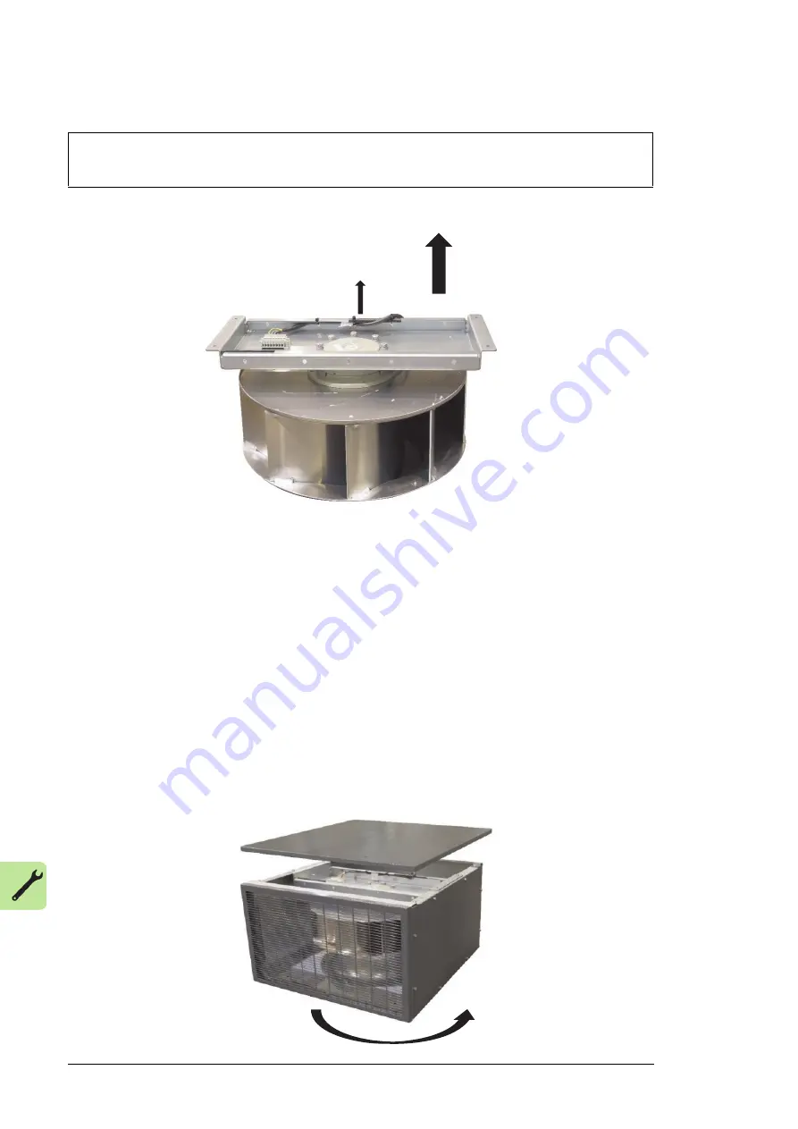
7. Remove the hex-head screws which attach the support beam to the impeller.
8. Disconnect the power cable from the connector on the support beam.
9. Mount the new impeller to the support beam.
10. Connect the wires of the fan motor cable to the terminal block according to the
electrical drawings.
11. Proceed in reverse order as previously described to reinstall the impeller with the
support beam.
12. Check by hand for proper fan rotation before energizing the drive.
13. When the work is completed the drive can be started up again. See Chapter
Operation, Energizing and starting the drive.
14. Check visually the direction of fan rotation when starting the drive. The correct rotation
direction please refer to arrow direction posted on fan box.
* Depends on site situation, ACS580MV fan box can be mounted backward, the screw
positions are compatible between fan box and cabinet top plate. The procedure can refer
to instruction above. For details of the AC fan box outline information, see
ACS580MV Air
duct interface Outline Drawing of AC Fan Box
.
NOTICE
Type and quantity of the hex-head screws depend on the impeller model.
M10X25
combination
screw
Summary of Contents for ACS580MV
Page 1: ...ABB industrial drives Hardware manual ACS580MV drives 200 kW to 6300 kW 6 kV to 11 kV...
Page 4: ......
Page 10: ...10...
Page 50: ...50 Control system and interfaces...
Page 52: ...52 Guidelines for planning the electrical installation...
Page 77: ...Electrical installation 77 Power cable entry from top 1 screen extensions to ground 1...
Page 90: ...90 Installation checklist...
Page 142: ...142 Maintenance...
Page 144: ......
Page 146: ...Contact us 2UBB004520 Rev E EN 2019 06 27 www abb com drives www abb com drivespartners...


