Hardware description
30
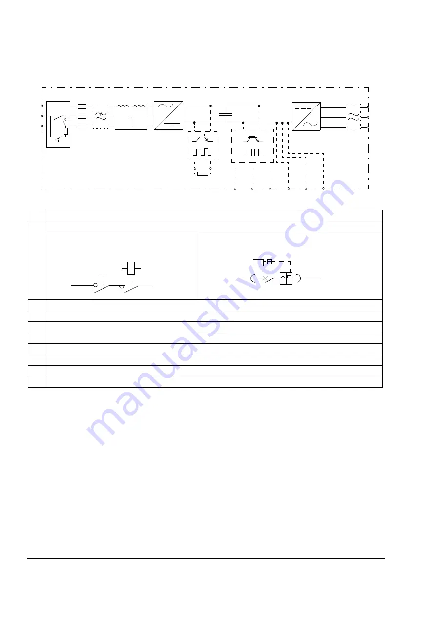
Block diagram of the main circuit with options
L1
L2
L3
U2
V2
W2
5)
6)
2)
R1.1 R2.1 R3.1 R1.2 R2.2 R3.2
7)
1)
No. Description
1
Main switch and disconnector and charging circuit
Drives of frame sizes R7i+R7i and R8i+R8i are
equipped with a main switch disconnector and
contactor:
Drives of frame sizes n×R8i+n×R8i are equipped with an air
circuit breaker:
2
Optional EMC filter (+E202)
3
LCL filter
4
Supply module
5
Brake chopper (D150)
6
Brake resistors (D151)
7
3-phase brake chopper (D152)
8
Inverter module. The module is equipped with du/dt as standard. For frame R7i, the filter is optional (+E205)
9
Sine filter (E206)
RMIO
U<
3)
4)
8)
9)
Summary of Contents for ACS800-17LC
Page 1: ...ABB industrial drives Hardware manual ACS800 17LC Drives 55 to 5200 kW ...
Page 4: ......
Page 10: ...Update notice 6 ...
Page 18: ...Table of contents 12 ...
Page 26: ...Safety instructions 20 ...
Page 32: ...Introduction to the manual 26 ...
Page 60: ...Hardware description 54 ...
Page 74: ...Mechanical installation 68 ...
Page 114: ...Electrical installation 108 ...
Page 142: ...Maintenance 136 ...
Page 150: ...Internal cooling circuit 144 ...
Page 179: ...Dimensions 173 Frame sizes R7i R7i and R8i R8i bottom entry exit ...
Page 180: ...Dimensions 174 Frame sizes R7i R7i and R8i R8i marine units C121 ...
Page 182: ...www abb com drives www abb com drivespartners Contact us 3AUA0000065339 Rev B EN 2016 06 07 ...

