Hardware description
35
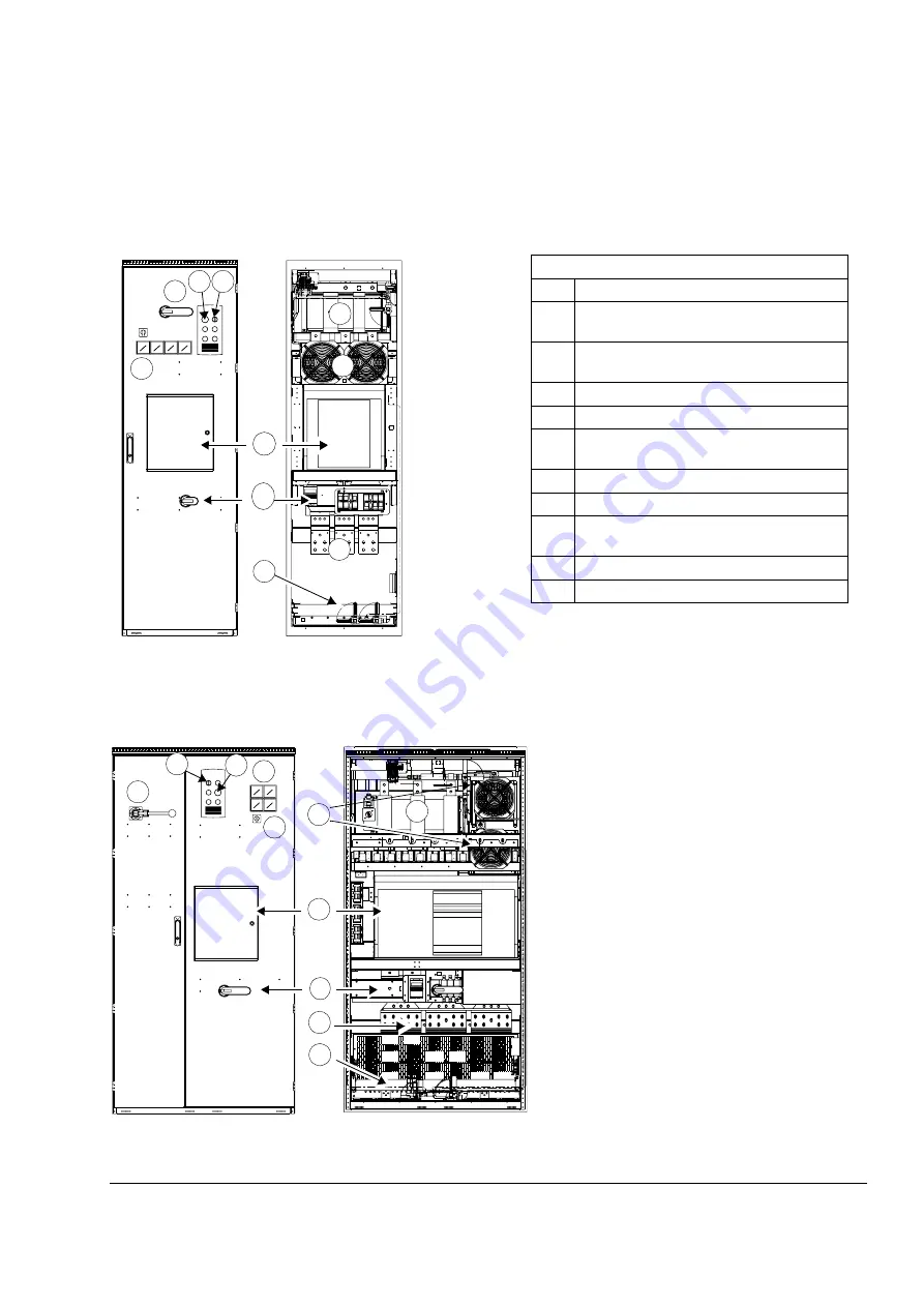
Main switch disconnecter cubicle layout (frames 2×R8i+2×R8i and up)
600 mm wide cubicle
1000 mm wide cubicle
Door closed
Door open
600 mm wide cubicle
No.
Description
1
Operating switch of the supply unit (Off/
On/Start)
2
Emergency stop reset push button (option
+G331)
3
Handle of grounding switch (F259)
4
Meters (oG335, +3G335, +G334)
5
Main switch disconnector (air circuit
breaker)
6
Charging circuit switch and handle
7
Busbars for input power cables
8
PE main busbar of the cabinet (behind the
cooling liquid pipe)
9
Heat exchanger and fans
10
Grounding switch (F259)
4
6
5
9
10
8
7
3
1
2
Doors closed
Doors open
4
3
6
5
10
8
7
9
3
2
1
Summary of Contents for ACS800-17LC
Page 1: ...ABB industrial drives Hardware manual ACS800 17LC Drives 55 to 5200 kW ...
Page 4: ......
Page 10: ...Update notice 6 ...
Page 18: ...Table of contents 12 ...
Page 26: ...Safety instructions 20 ...
Page 32: ...Introduction to the manual 26 ...
Page 60: ...Hardware description 54 ...
Page 74: ...Mechanical installation 68 ...
Page 114: ...Electrical installation 108 ...
Page 142: ...Maintenance 136 ...
Page 150: ...Internal cooling circuit 144 ...
Page 179: ...Dimensions 173 Frame sizes R7i R7i and R8i R8i bottom entry exit ...
Page 180: ...Dimensions 174 Frame sizes R7i R7i and R8i R8i marine units C121 ...
Page 182: ...www abb com drives www abb com drivespartners Contact us 3AUA0000065339 Rev B EN 2016 06 07 ...


