Planning the electrical installation
73
High-output motors and IP 23 motors
For motors with higher rated output than what is stated for the particular frame size in EN 50347 (2001)
and for IP23 motors, the requirements of ABB random-wound motor series (for example M3AA, M3AP,
M3BP) are given below. For non-ABB motor types, see the basic table above and apply the
requirements of range
100 kW <
P
N
< 350 kW
to motors with
P
N
< 100 kW. Apply the requirements of
range
P
N
> 350 kW
to motors within the range
100 kW <
P
N
< 350 kW
. In other cases, consult the
motor manufacturer.
HXR and AMA motors
All AMA machines (manufactured in Helsinki) for drive systems have form-wound windings. All HXR
machines manufactured in Helsinki starting 1.1.1998 have form-wound windings.
ABB motors of types other than M2_, M3_, HX_ and AM_
Use the selection criteria given for non-ABB motors.
When DC link voltage is increased with parameter settings
If the intermediate circuit DC voltage is increased with the IGBT supply control program parameter
settings, select the motor insulation system according to the increased DC voltage level, especially in
the 500 V supply voltage range.
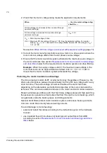
Calculating the rise time and the peak line-to-line voltage
The peak line-to-line voltage at the motor terminals generated by the drive as well as the voltage rise
time depend on the cable length. The requirements for the motor insulation system given in the table
are “worst case” requirements covering installations with 30 metre and longer cables. The rise time can
be calculated as follows: t = 0.8 ·
Û
LL
/(du/dt). Read
Û
LL
and du/dt from the diagrams below. Multiply
the values of the graph by the supply voltage (
U
N
). In case of drives with resistor braking, the
Û
LL
and
du/dt values are approximately 20% higher.
M
an
u
fa
ct
u
re
r
Motor type
Nominal mains
voltage (AC line
voltage)
Requirement for
Motor insulation
system
ABB du/dt filter, insulated N-end bearing and ABB common mode
filter
P
N
< 100 kW
100 kW <
P
N
< 200 kW
P
N
> 200 kW
P
N
< 140 hp
140 hp <
P
N
< 268 hp
P
N
> 268 hp
A
B
B
Random-
wound
U
N
< 500 V
Standard
-
+ N
+ N + CMF
500 V <
U
N
< 600 V Standard
+ du/dt
+ du/dt + N
+ du/dt + N + CMF
or
Reinforced
-
+ N
+ N + CMF
600 V <
U
N
< 690 V Reinforced
+ du/dt
+ du/dt + N
+ du/dt + N + CMF
Summary of Contents for ACS800-17LC
Page 1: ...ABB industrial drives Hardware manual ACS800 17LC Drives 55 to 5200 kW ...
Page 4: ......
Page 10: ...Update notice 6 ...
Page 18: ...Table of contents 12 ...
Page 26: ...Safety instructions 20 ...
Page 32: ...Introduction to the manual 26 ...
Page 60: ...Hardware description 54 ...
Page 74: ...Mechanical installation 68 ...
Page 114: ...Electrical installation 108 ...
Page 142: ...Maintenance 136 ...
Page 150: ...Internal cooling circuit 144 ...
Page 179: ...Dimensions 173 Frame sizes R7i R7i and R8i R8i bottom entry exit ...
Page 180: ...Dimensions 174 Frame sizes R7i R7i and R8i R8i marine units C121 ...
Page 182: ...www abb com drives www abb com drivespartners Contact us 3AUA0000065339 Rev B EN 2016 06 07 ...


