Electrical installation
100
Connecting external power supply for the auxiliary circuits
Frames R7i×R7i and R8i×R8i
As standard, the drive auxiliary circuit is supplied from the main power supply of the
drive through an auxiliary voltage transformer. You do not need to connect any
external auxiliary power supply for the auxiliary circuits.
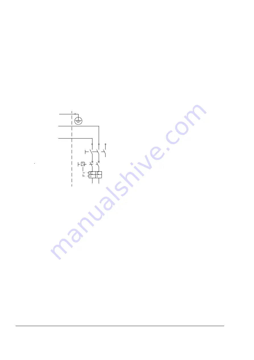
If the drive is equipped with G307 (Terminals for connecting external control
voltage), connect the external power supply as shown in the figure below. The circuit
breaker Q200 is located in the Incoming cubicle of the drive. Maximum fuse: 16 A.
For the current consumption of the the circuitry, see section
on page
>
L
N
Q200
3
2
1
PE
N
L
Power supply for control circuitry (units with G307 for UPS )
>
Summary of Contents for ACS800-17LC
Page 1: ...ABB industrial drives Hardware manual ACS800 17LC Drives 55 to 5200 kW ...
Page 4: ......
Page 10: ...Update notice 6 ...
Page 18: ...Table of contents 12 ...
Page 26: ...Safety instructions 20 ...
Page 32: ...Introduction to the manual 26 ...
Page 60: ...Hardware description 54 ...
Page 74: ...Mechanical installation 68 ...
Page 114: ...Electrical installation 108 ...
Page 142: ...Maintenance 136 ...
Page 150: ...Internal cooling circuit 144 ...
Page 179: ...Dimensions 173 Frame sizes R7i R7i and R8i R8i bottom entry exit ...
Page 180: ...Dimensions 174 Frame sizes R7i R7i and R8i R8i marine units C121 ...
Page 182: ...www abb com drives www abb com drivespartners Contact us 3AUA0000065339 Rev B EN 2016 06 07 ...


