Technical data
161
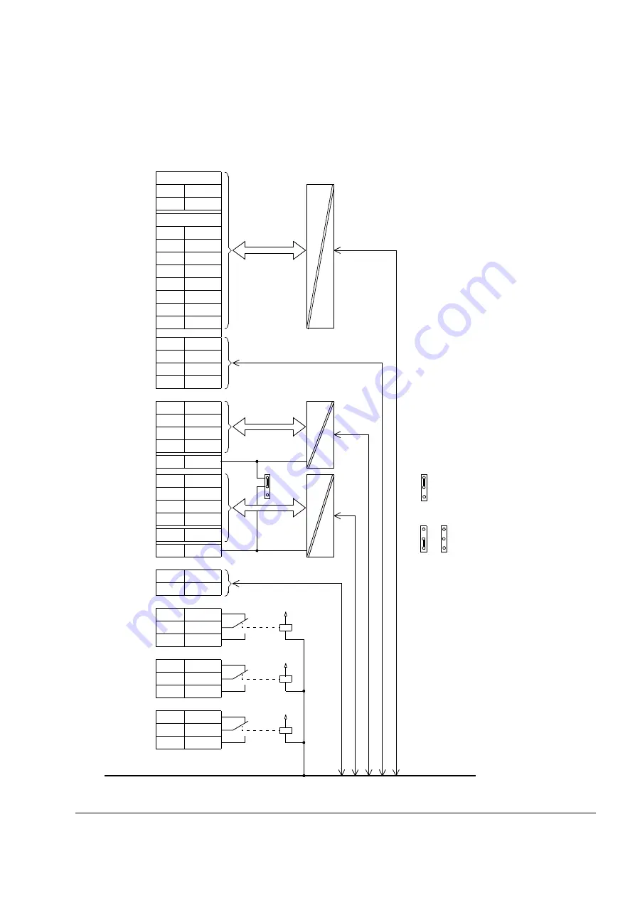
Isolation and grounding diagram
X20
1
VREF-
2
AGND
X21
1
VREF+
2
AGND
3
AI1+
4
AI1-
5
AI2+
6
AI2-
7
AI3+
8
AI3-
9
AO1+
10
AO1-
11
AO2+
12
AO2-
X22
1
DI1
2
DI2
3
DI3
4
DI4
9
DGND1
5
DI5
6
DI6
7
+24VD
8
+24VD
11
DIIL
10
DGND2
X23
1
+24 V
2
GND
X25
1
RO1
2
RO1
3
RO1
X26
1
RO2
2
RO2
3
RO2
X27
1
RO3
2
RO3
3
RO3
Common mode
voltage between
channels ±15 V
J1
(Test voltage: 500 V AC)
or
Jumper J1 settings:
All digital inputs share a common
ground. This is the default setting.
Grounds of input groups
DI1…DI4 and DI5/DI6/DIIL
are separate (insulation
voltage 50 V).
Ground
(Test voltage:
4 kV AC)
Summary of Contents for ACS800-17LC
Page 1: ...ABB industrial drives Hardware manual ACS800 17LC Drives 55 to 5200 kW ...
Page 4: ......
Page 10: ...Update notice 6 ...
Page 18: ...Table of contents 12 ...
Page 26: ...Safety instructions 20 ...
Page 32: ...Introduction to the manual 26 ...
Page 60: ...Hardware description 54 ...
Page 74: ...Mechanical installation 68 ...
Page 114: ...Electrical installation 108 ...
Page 142: ...Maintenance 136 ...
Page 150: ...Internal cooling circuit 144 ...
Page 179: ...Dimensions 173 Frame sizes R7i R7i and R8i R8i bottom entry exit ...
Page 180: ...Dimensions 174 Frame sizes R7i R7i and R8i R8i marine units C121 ...
Page 182: ...www abb com drives www abb com drivespartners Contact us 3AUA0000065339 Rev B EN 2016 06 07 ...


