background image

ACS850 

Common DC configuration application guide  


Summary of Contents for ACS850 series

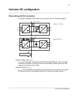
Page 1: ...ACS850 Common DC configuration application guide...

Page 2: ......

Page 3: ...ACS850 Common DC configuration application guide 3AUA0000073108 REV A EN EFFECTIVE 22 3 2010 2010 ABB Oy All rights reserved...

Page 4: ......

Page 5: ...otor or motor cable Even when input power is not applied to the drive externally supplied control circuits may carry dangerous voltages Always ensure by measuring that there is no voltage in the drive...

Page 6: ...6 Safety instructions...

Page 7: ...ec max 15 Chokes braking choppers and charging circuits 16 Power requirements 16 DC link power Pdc mot of motoring axis 17 DC link power Pdc gen of regenerating axis 17 Average motoring power Pmot ave...

Page 8: ...wer ratings 30 Single braking chopper 30 Multiple braking choppers 31 Braking resistor selection 31 Single braking resistor 31 Multiple braking resistors 31 Braking resistor types 32 General system de...

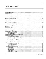
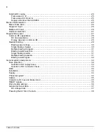
Page 9: ...9 Table of contents...

Page 10: ...worldwide Both SI and imperial units are shown wherever appropriate Categorization according to the frame size Some instructions technical data and dimensional drawings that only concern certain frame...

Page 11: ...11 Introduction to the manual...

Page 12: ...aking resistors if the simultaneous regenerative power is not higher than the motoring power A DC link energy storage can be used for short dynamic braking energy pulses to avoid the need for an exter...

Page 13: ...choke cases the input cable s cross sectional area and length Charging methods vary depending on the converter size Because of this in some installations the supplies of the frame sizes A D should be...

Page 14: ...D AC input current Select the mains choke s if necessary charging capacity multiple AC input single AC input Select the drive module s to be connected to the AC supply average and maximum total regene...

Page 15: ...e rectifier power Prec ave Prec ave is the maximum average DC power that the input bridge of a drive can supply The actual average DC power taken from the input bridge should be lower than this value...

Page 16: ...link voltage level which corresponds to the nominal 400 V AC supply voltage Uac In case of other DC voltage levels Udc the Prec values in the table are multiplied by Udc 540 where ac dc U U 35 1 Choke...

Page 17: ...can be used Pm motor mechanical shaft power T torque Nm on motor shaft n motor shaft speed rpm DC link power Pdc gen of regenerating axis Pdc gen is now the power supplied from the regenerating motor...

Page 18: ...erative power Pgen ave Pgen ave is the average of the regenerating DC link power over the whole cycle This power must be dissipated in the braking resistor s or fed back to the AC supply Pgen ave shou...

Page 19: ...uration can be used Single AC input frames E0 G To determine whether it is possible to leave other converters unconnected to the main supply see chapter Checking the charging circuit capacity The foll...

Page 20: ...ust be connected together via a contactor because the converters have different charging circuits The DC contactors are switched on after all of the DC links are charged and the converters are in the...

Page 21: ...nd the charging circuit s of the drive s are connected to the supply charge of all the capacitor banks The charging circuit data for each drive module is shown in the following table R Rmin ACS850 Typ...

Page 22: ...ws n min min min R R R R 1 1 1 1 2 1 L Rmin values Rmin1 Rmin2 are the individual minimum resistance values of the drive modules connected to the AC supply The following condition must be fulfilled Rt...

Page 23: ...arging circuit of the connected converter must be able to withstand the total charging energy Etot i e Erconnected Etot The charging energy of the DC link capacitors of a single converter is calculate...

Page 24: ...5600 J External DC supply The drive modules can also be supplied from an external DC supply This can be the case if the needed DC link power can not be handled with any available drive module In this...

Page 25: ...drive modules have internal charging circuits in series with DC link capacitors Frame sizes E0 E and G In frame sizes E0 E and G the charging circuit is in parallel with the input bridge Separate cha...

Page 26: ...ine current Imot ave ac ave mot mot ave U P I 3 15 1 Define the peak motoring line current Imot max ac max mot max mot U P I 3 15 1 The factor 1 15 covers the effects of the line side power factor the...

Page 27: ...rements for harmonic distortion according to standards IEC 61000 3 2 IEC 610003 4 and IEC 610003 12 are typically fulfilled A more accurate harmonics analysis can be made with the sizing tool DriveSiz...

Page 28: ...duced DC link capacitance Each drive module has its own capacitor bank The capacitance value of each drive size is given in the table below Cdc Cdc ACS850 Type F ACS850 Type F 03A0 5 03A6 5 120 103A 5...

Page 29: ...m dc U DC link voltage level where the braking choppers are not yet activated 780 V DC lim dc U To determine whether the energy capacity is adequate that is the selected Udc lim voltage level is not r...

Page 30: ...00 2 521A 5 234 1 8 602A 5 210 1 35 693A 5 720A 5 170 1 Pbr max the maximum braking power of the chopper The chopper withstands this braking power for 1 second within every 10 seconds Pbr cont the int...

Page 31: ...er data of the drive module The selected resistance value Rbr should also fulfil the peak braking power requirements In the following calculations the value of Udc is 840 V DC max gen dc br min P U R...

Page 32: ...adequate for the average regenerative power i R N ave gen cont br cont br i cont br P P P P P 2 1 Where PN R i is the nominal power rating of the individual resistor steady state continuous load For m...

Page 33: ...le protection Selection of DC connection fuses In the common DC system each DC connection must be equipped with fuses Fuses are needed in both branches The general guidelines for the selection of DC l...

Page 34: ...e AC supply of the common DC system but the rules to meet the different EMC categories are not available Installation See the relevant hardware manual for the installation mechanical and electrical gu...

Page 35: ...ainst brake chopper faults Contactors must be capable of cutting off the DC current The maximum operational voltage over the contactor is the DC voltage during the braking i e 1 21 1 35 U1 DC current...

Page 36: ...ENERATING LIM to limit the maximum power The calculated braking power can also be used as the parameter value of 20 13 P GENERATING LIM When brake chopper is used set parameter 48 01 BC ENABLE This ac...

Page 37: ...uvc 50 V min 350 382 V Braking chopper limit low UDC brcl UDC ovc 30 V 645 V Braking chopper limit high UDC brch UDC ovc 30 V 705 V UDC in the Value column where the values are defined is based on th...

Page 38: ...limits the braking chopper in the drive module is activated if the braking chopper is enabled when the DC link voltage reaches the low level UDC brcl If the DC link voltage level reaches the high leve...

Page 39: ...EFFECTIVE 22 3 2010 3AUA0000073108 REV A EN...

Reviews: