


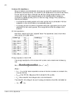

16
P
rec,ave
P
rec,max
ACS850 Type
kW kW
03A0-5, 03A6-5, 04A8-5, 06A0-5
3.5
4.4
08A0-5 4.7
5.9
010A-5 6.5
8.1
014A-5, 018A-5
10.8
13.5
025A-5, 030A-5, 035A-5
20.5
25.7
044A-5, 050A-5
29.2
36.5
061A-5, 078A-5, 094A-5
52.9
66.2
103A-5 61.0
77.1
144A-5 85.3
90.1
166A-5 98.2
103.6
202A-5 119.3
133.9
225A-5 133.3
154.8
260A-5 152.2
197.3
290A-5 171.7
215.4
430A-5 260.2
315.6
521A-5 315.3
351.3
602A-5 364.5
442.8
693A-5 419.5
511.2
720A-5 435.7
511.2
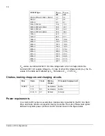
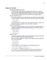
P
rec
values are defined at 540 V DC link voltage level, which corresponds to the
nominal 400 V AC supply voltage
U
ac
. In case of other DC voltage levels (
U
dc
), the
P
rec
values in the table are multiplied by
U
dc
/540 where
ac
dc
U
.
U
×
≈
35
1
.
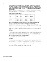
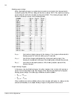
Chokes, braking choppers and charging circuits
Drive Frame
Choke
Braking
chopper
DC supply charging circuit
A, B
-
As standard
Built-in
C, D
DC
As standard
Built-in
ACS850
E0, E, G
AC
Optional
External
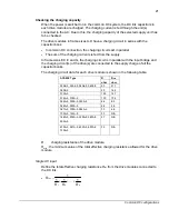
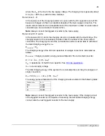
Power requirements
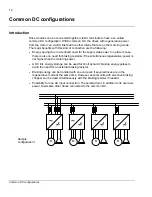
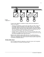
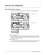
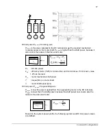
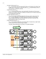
In a common DC system, several drive modules are connected to the DC link. Each
drive and motor has its own specific load cycle profile. The sum of these load cycles
defines the system power profile in the DC link as shown in the figure below.
Common DC configurations
Summary of Contents for ACS850 series
Page 1: ...ACS850 Common DC configuration application guide...
Page 2: ......
Page 4: ......
Page 6: ...6 Safety instructions...
Page 9: ...9 Table of contents...
Page 11: ...11 Introduction to the manual...


