


17
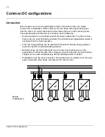
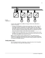
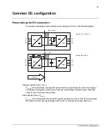
Common DC configurations
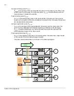
DC link power P
dc,mot
of motoring axis
P
dc,mot
is the power supplied to the DC terminals to get the required mechanical
motoring power on the motor shaft.
P
dc,mot
is higher than the shaft power, because it
also covers the losses in the drive and motor.
P
dc
: DC link power
k
eff
: efficiency factor (1/eff) to include drive and motor losses. If not known, value
1.25 can be used.
P
m
: motor mechanical shaft power
T
: torque (Nm) on motor shaft
n
: motor shaft speed (rpm)
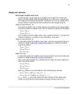
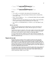
DC link power P
dc,gen
of regenerating axis
P
dc,gen
is now the power supplied from the regenerating motor to the DC terminals.
P
dc,gen
is lower than the shaft power, because the shaft power now covers also the
losses in the drive and motor.
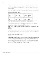
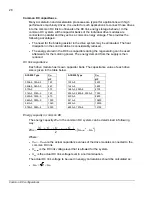
Based on the system power profile, the following system level DC link power values
are defined.
Drive
A
Drive
B
Drive
C
M
M
M
P
dc,mot
Drive losses
Motor losses
P
m
m
eff
mot
,
dc
P
k
P
×
=
9550
n
T
)
kW
(
P
m
×
≈
P
m
Drive losses
Motor losses
P
dc,gen
eff
m
gen
,
dc
k
P
P
×
=
Summary of Contents for ACS850 series
Page 1: ...ACS850 Common DC configuration application guide...
Page 2: ......
Page 4: ......
Page 6: ...6 Safety instructions...
Page 9: ...9 Table of contents...
Page 11: ...11 Introduction to the manual...


