


26
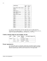
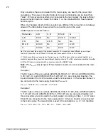
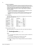
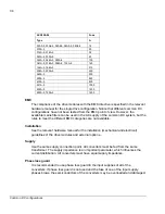
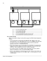
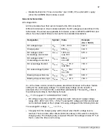
Mains choke data
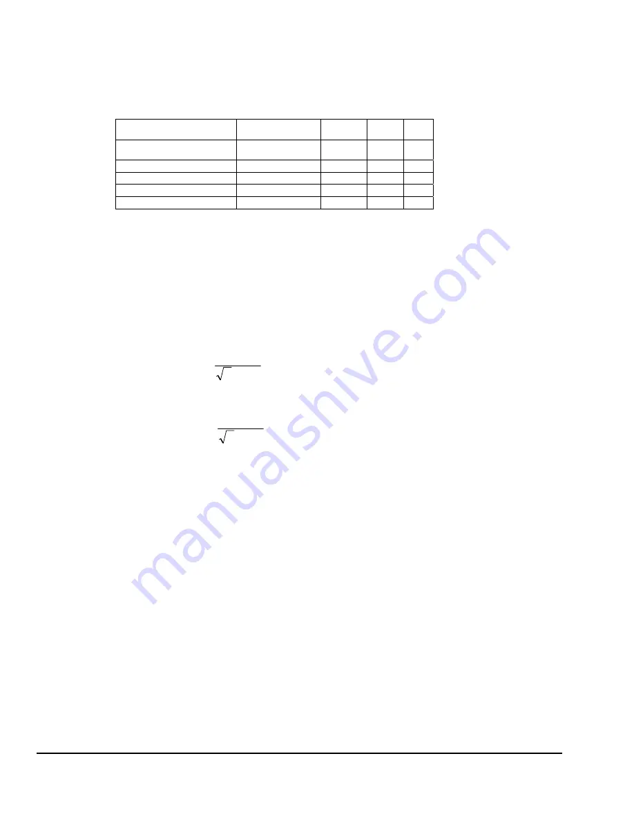
Data for the mains chokes is listed in the table below. Drive types not listed below have
a built-in choke as standard.
Frame Choke
type
L
I
th
I
max
ACS850
µ
H
A A
03A0-5, 03A6-5
CHK-01
6370
4.2
6.2
04A8-5, 06A0-5, 08A0-5 CHK-02
4610 7.6 11.4
010A-5, 014A-5
CHK-03
2700
13.1
19.6
018A-5 CHK-04
1475
22.0
26.3
L
: mains choke nominal inductance
I
th
: the maximum allowed continuous current (rms) at 55°C ambient temperature
I
max
: the maximum allowed short time current (rms). This current is allowed for
maximum of 10 s.
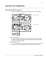
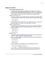
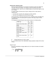
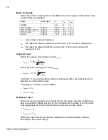
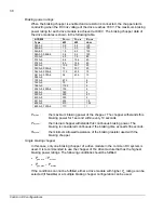
Single AC input
Define the
average motoring line current I
mot,ave
•
ac
ave
,
mot
mot,ave
U
P
.
I
×
×
=
3
15
1
Define the
peak motoring line current I
mot,max
•
ac
,max
mot
max
mot,
U
P
.
I
×
×
=
3
15
1
The factor 1.15 covers the effects of the line side power factor, the current harmonic
distortion, and the rectifier losses.
The following conditions must be fulfilled:
•
th
ave
,
mot
I
I
<
•
max
,max
mot
I
I
<
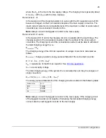
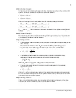
Multiple AC input
If two or more drive modules are connected to the AC supply, the same conditions as
above must still be fulfilled, but now for each individual drive module (i) and its mains
choke separately. All of the connected drives must have a mains choke.
•
)
i
(
th
)
i
(
ave
,
mot
I
I
<
•
)
i
max(
)
i
,max(
mot
I
I
<
Where the total motoring line current is allocated to the individual drive modules
according to their power ratings:
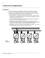
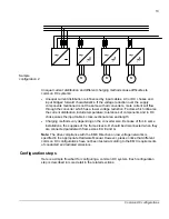
Common DC configurations
Summary of Contents for ACS850 series
Page 1: ...ACS850 Common DC configuration application guide...
Page 2: ......
Page 4: ......
Page 6: ...6 Safety instructions...
Page 9: ...9 Table of contents...
Page 11: ...11 Introduction to the manual...


