Fieldbus control through the embedded fieldbus interface (EFB) 385
Setting up the embedded fieldbus interface
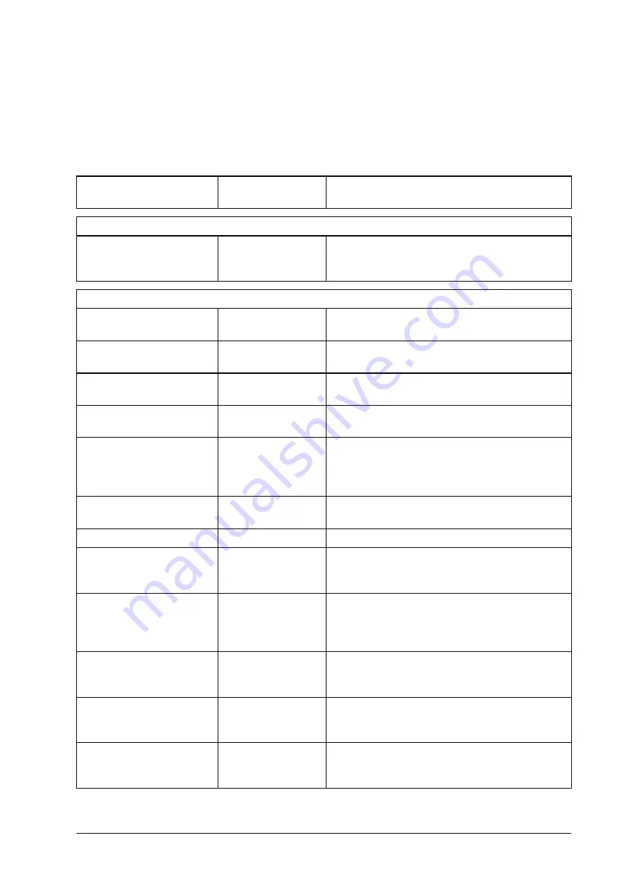
Set the drive up for the embedded fieldbus communication with the parameters
shown in the table below. The
Setting for fieldbus control
column gives either the
value to use or the default value. The
Function/Information column
gives a
description of the parameter.
Parameter
Setting for
fieldbus control
Function/Information
COMMUNICATION INITIALIZATION
Initializes embedded fieldbus communication.
Drive-to-drive link operation is automatically
disabled.
EMBEDDED MODBUS CONFIGURATION
1 (default)
Node address. There must be no two nodes
with the same node address online.
(default) Defines the communication speed of the link.
Use the same setting as in the master station.
(default) Selects the parity and stop bit setting. Use the
same setting as in the master station.
(default)
Defines the action taken when a
communication loss is detected.
(default)
Enables/disables communication loss
monitoring and defines the means for
resetting the counter of the communication
loss delay.
3.0 s (default)
Defines the timeout limit for the
communication monitoring.
0 ms (default)
Defines a response delay for the drive.
(default),
Selects the control profile used by the drive.
See section
Basics of the embedded fieldbus
(page
).
…
…
,
Selects the reference and actual value types.
With the
setting, the type is selected
automatically according to the currently active
drive control mode.
EFB status word
transparent
source
Defines the source of status word when
.
Defines the source of actual value 1 when
or
Defines the source of actual value 2 when
or
Summary of Contents for ACS860
Page 1: ... ABB INDUSTRIAL DRIVES ACS860 primary control program Firmware manual ...
Page 4: ......
Page 10: ...10 Table of contents ...
Page 18: ...18 Using the control panel ...
Page 24: ...24 Control locations and operating modes ...
Page 54: ...54 Program features ...
Page 78: ...78 Program features ...
Page 90: ...90 Application macros ...
Page 342: ...342 Additional parameter data ...
Page 380: ...380 Fault tracing ...
Page 381: ...Fault tracing 381 ...
Page 382: ...382 Fault tracing ...
Page 436: ...436 Control chain diagrams ...


