68 Planning the electrical installation
Motor cable shield
If the motor cable shield is used as the sole protective earth conductor of the motor,
ensure that the conductivity of the shield is sufficient. See subsection
above, or IEC 61439-1. To effectively suppress radiated and conducted radio-
frequency emissions, the cable shield conductivity must be at least 1/10 of the phase
conductor conductivity. The requirements are easily met with a copper or aluminum
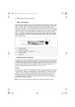
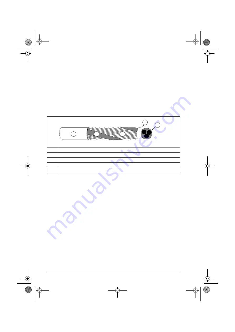
shield. The minimum requirement of the motor cable shield of the drive is shown
below. It consists of a concentric layer of copper wires with an open helix of copper
tape or copper wire. The better and tighter the shield, the lower the emission level
and bearing currents.
Additional US requirements
Use type MC continuous corrugated aluminum armor cable with symmetrical grounds
or shielded power cable for the motor cables if metallic conduit is not used. For the
North American market, 600 V AC cable is accepted for up to 500 V AC. 1000 V AC
cable is required above 500 V AC (below 600 V AC). For drives rated over 100
amperes, the power cables must be rated for 75
°
C (167
°
F).
Conduit
Couple separate parts of a conduit together: bridge the joints with a ground conductor
bonded to the conduit on each side of the joint. Also bond the conduits to the drive
enclosure and motor frame. Use separate conduits for input power, motor, brake
resistor, and control wiring. When conduit is employed, type MC continuous
corrugated aluminum armor cable or shielded cable is not required. A dedicated
ground cable is always required.
Note
: Do not run motor wiring from more than one drive in the same conduit.
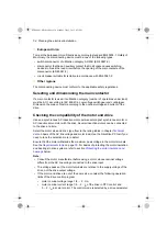
1
Insulation jacket
2
Copper wire screen
3
Helix of copper tape or copper wire
4
Inner insulation
5
Cable core
1
2
3
4
5
ACS880-01 HW.book Page 68 Monday, July 1, 2013 4:51 PM
Summary of Contents for ACS880-01 Series
Page 4: ...ACS880 01 HW book Page 4 Monday July 1 2013 4 51 PM...
Page 12: ...12 ACS880 01 HW book Page 12 Monday July 1 2013 4 51 PM...
Page 20: ...20 Safety instructions ACS880 01 HW book Page 20 Monday July 1 2013 4 51 PM...
Page 26: ...26 Introduction to the manual ACS880 01 HW book Page 26 Monday July 1 2013 4 51 PM...
Page 80: ...80 Planning the electrical installation ACS880 01 HW book Page 80 Monday July 1 2013 4 51 PM...
Page 96: ...96 Electrical installation 8b R8 R9 ACS880 01 HW book Page 96 Monday July 1 2013 4 51 PM...
Page 98: ...98 Electrical installation 16 13 R8 R9 ACS880 01 HW book Page 98 Monday July 1 2013 4 51 PM...
Page 118: ...118 Start up ACS880 01 HW book Page 118 Monday July 1 2013 4 51 PM...
Page 120: ...120 Fault tracing ACS880 01 HW book Page 120 Monday July 1 2013 4 51 PM...
Page 131: ...Maintenance 131 3 4 5 3 ACS880 01 HW book Page 131 Monday July 1 2013 4 51 PM...
Page 172: ...172 Technical data ACS880 01 HW book Page 172 Monday July 1 2013 4 51 PM...
Page 196: ...196 Dimension drawings ACS880 01 HW book Page 196 Monday July 1 2013 4 51 PM...
Page 209: ...Safe Torque off function 209 Certificate ACS880 01 HW book Page 209 Monday July 1 2013 4 51 PM...
Page 210: ...210 Safe Torque off function ACS880 01 HW book Page 210 Monday July 1 2013 4 51 PM...
Page 220: ...220 Resistor braking ACS880 01 HW book Page 220 Monday July 1 2013 4 51 PM...

