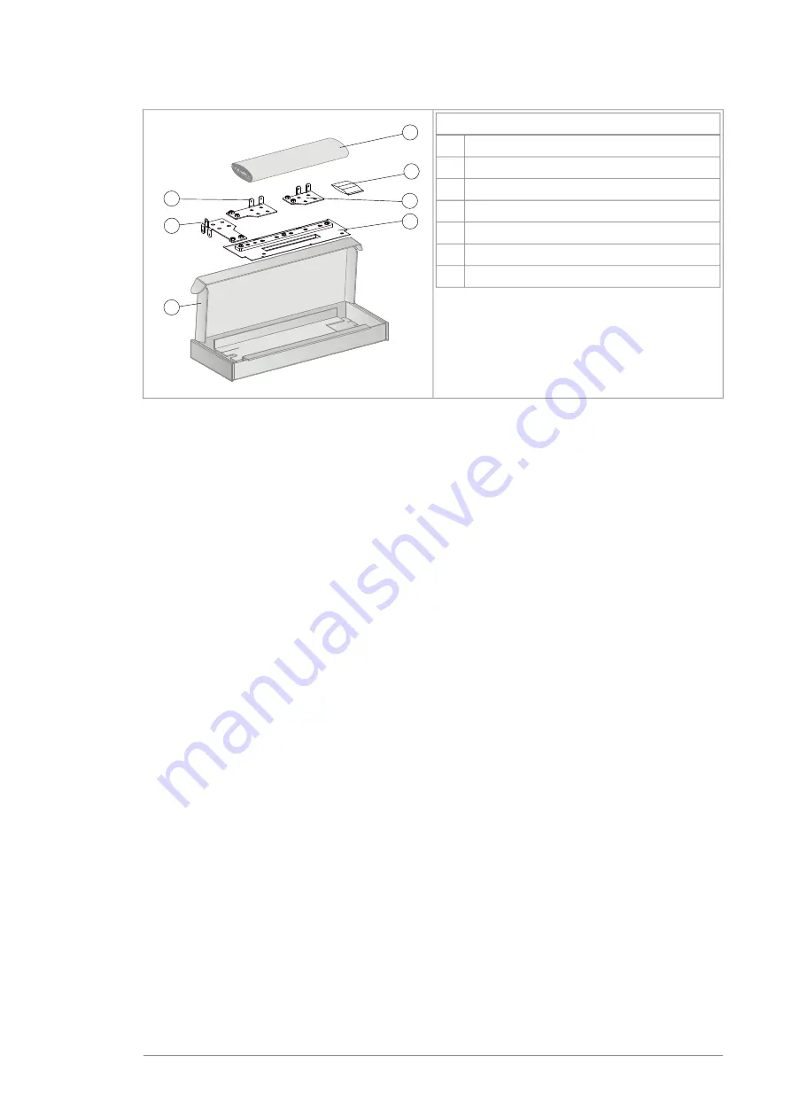
Box B3 contents (H370)
Metallic shroud with ground bar
1
Paper fill
2
Input cable connection terminal L3/W1
3
Input cable connection terminal L2/V1
4
Input cable connection terminal L1/U1
5
Cardboard box
6
Screws and insulators in a plastic bag
7
3AXD5000009522
3
6
4
2
5
1
7
Lift the drive from the lifting points
Refer to image A in section
Step-by-step drawings for an installation example (page 31)
.
Reform the capacitors
If the drive has not been powered up for a year or more, you must reform the DC link
capacitors. Refer to
or contact ABB technical support.
Ensure the cooling
See section
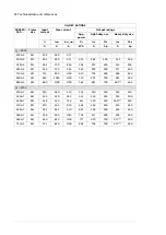
Losses and cooling data (page 25)
for the losses and required cooling air
flow through the drive.
Install the drive module onto a mounting plate
See figure B in chapter
Step-by-step drawings for an installation example (page 31)
Install the top metallic shroud and back plastic shrouds
See figures C and D in chapter
Step-by-step drawings for an installation
•
Remove the sheeting from the clear plastic shrouds from both sides.
•
Install the top metallic shroud to the drive module.
•
Install the back shrouds to the drive module.
Measure the insulation resistance of the input and motor
cables and the motor
See figures F and G.
Before you connect the input power cable to the drive, measure its insulation resistance
according to local regulations.
Quick installation and start-up instructions 13
Summary of Contents for ACS880-04F
Page 1: ...ABB INDUSTRIAL DRIVES ACS880 04F drive modules Quick installation and start up guide...
Page 2: ......
Page 4: ......
Page 6: ...6...


