Product overview
The ACS880-04FXT is a drive module package (drive) for controlling asynchronous AC
induction motors, permanent magnet motors and AC induction servomotors. The drive
consists of two drive modules (ACS880-04F +P943) and a separate control unit.
The drive can measure the output currents of the drive modules and thus control the total
output and input currents. It cannot control the input current sharing between the modules.
See section
Drive connection examples (page 27)
for the supply side protection.
There needs to be enough inductance at the output of the modules for the output currents
to be balanced: the modules need to be equipped with optional d
u
/d
t
or sine filters, or long
enough motor cables from each drive module before connecting them together. See the
connection diagrams in
Connecting the power cables (frame size 2 x R11) (page 87)
.
Note:
All motor cables must be of equal type and length.
The DC links of the drive modules are to be connected together to make sure that the drive
operates correctly.
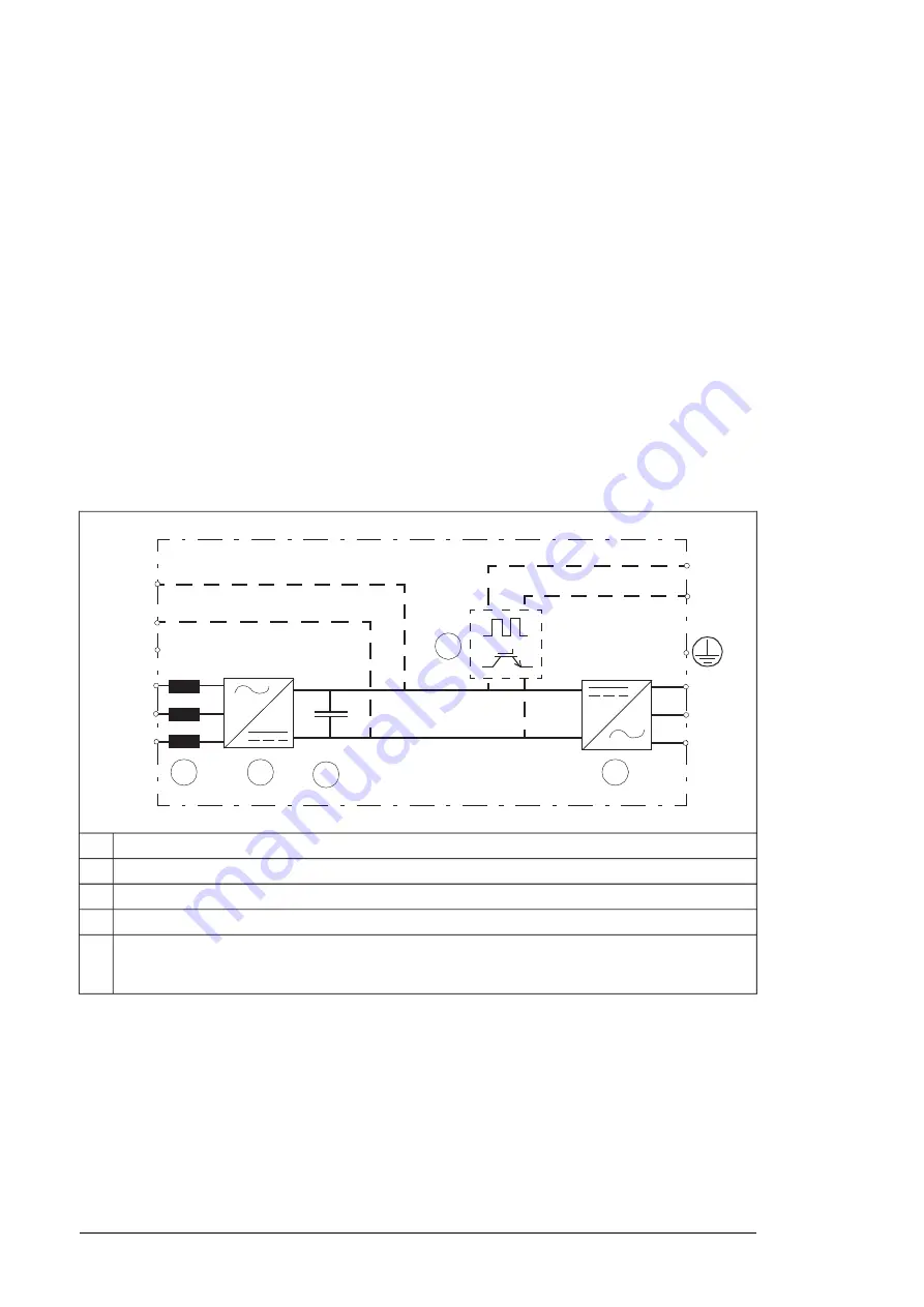
The main circuit of the drive module is shown below.
L1/U1
L2/V1
L3/W1
T1/U2
T2/V2
T3/W2
R-
R+
4
2
1
3
UDC-
UDC+
PE
5
ACS880-04
F
+P943
AC choke
1
Rectifier. Converts alternating current and voltage to direct current and voltage.
2
DC link. DC circuit between rectifier and inverter.
3
Inverter. Converts direct current and voltage to alternating current and voltage.
4
Brake chopper (D150). Conducts the surplus energy from the intermediate circuit of the drive to
the brake resistor when necessary. The chopper operates when the DC link voltage exceeds a certain
maximum limit. The voltage rise is typically caused by deceleration (braking) of a high inertia motor.
5
26 Operation principle and hardware description
Summary of Contents for ACS880-04FXT
Page 1: ... ABB INDUSTRIAL DRIVES ACS880 04FXT drive module packages Hardware manual ...
Page 2: ......
Page 4: ......
Page 40: ...40 ...
Page 54: ...54 ...
Page 82: ...82 ...
Page 86: ...M10 86 Electrical installation ...
Page 106: ...106 ...
Page 118: ...118 ...
Page 122: ...122 ...
Page 132: ...132 ...
Page 136: ...136 ...
Page 158: ...158 ...
Page 160: ...Standard configuration IP00 UL Type Open 160 Dimension drawings ...
Page 161: ...Drive module with optional support brackets IP00 UL Type Open Dimension drawings 161 ...
Page 163: ...Mounting plate opening 3AXD50000038119 Dimension drawings 163 ...
Page 164: ...3AXD50000038119 164 Dimension drawings ...
Page 182: ... Declaration of conformity 182 The Safe torque off function ...
Page 183: ...The Safe torque off function 183 ...
Page 184: ...184 ...


