4.
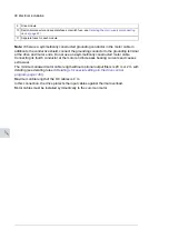
Connect the UDC terminals of the drive modules together. For the tightening torques,
see the technical data.
If the DC cables are run outside the cabinet, ground the cable shield 360° at one end
only.
~
~
T1/
T2/
T3/
U2
V2
W2
~
~
T1/ T2/ T3/
U2
V2
W2
UDC-
UDC+
L1 /
L2/
L3 /
U1
V1
W1
L1/
L2 / L3/
U1
V1
W1
UDC-
UDC+
5.
Connect the cable shields of the input cables and any separate ground conductors or
cables to the drive module ground terminal or to the cabinet PE busbar.
6.
Connect the phase conductors of the input cables to terminals L1/U1, L2/V1 and L3/W1
of the drive module. For the tightening torques, see the technical data.
Electrical installation 97
11
Summary of Contents for ACS880-04FXT
Page 1: ... ABB INDUSTRIAL DRIVES ACS880 04FXT drive module packages Hardware manual ...
Page 2: ......
Page 4: ......
Page 40: ...40 ...
Page 54: ...54 ...
Page 82: ...82 ...
Page 86: ...M10 86 Electrical installation ...
Page 106: ...106 ...
Page 118: ...118 ...
Page 122: ...122 ...
Page 132: ...132 ...
Page 136: ...136 ...
Page 158: ...158 ...
Page 160: ...Standard configuration IP00 UL Type Open 160 Dimension drawings ...
Page 161: ...Drive module with optional support brackets IP00 UL Type Open Dimension drawings 161 ...
Page 163: ...Mounting plate opening 3AXD50000038119 Dimension drawings 163 ...
Page 164: ...3AXD50000038119 164 Dimension drawings ...
Page 182: ... Declaration of conformity 182 The Safe torque off function ...
Page 183: ...The Safe torque off function 183 ...
Page 184: ...184 ...


