background image

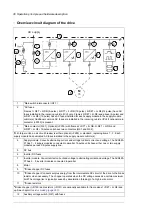
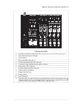
Auxiliary control cubicle (ACU) layout

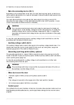
A layout example of the auxiliary control cubicle (ACU) is shown below. On the left: Swing-out
frame closed, detachable mounting plates in place. On the right: Swing-out frame open,
without detachable mounting plates.

40   Operation principle and hardware description

„

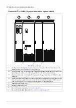
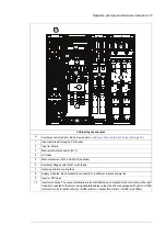
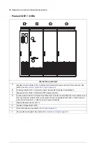
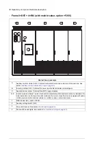
Auxiliary control cubicle (ACU) layout

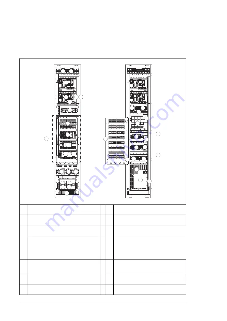
A layout example of the auxiliary control cubicle (ACU) is shown below.

1

Fuse-disconnectors F101. On the primary of 
transformer T101 (item

27

).

19 Lead-through for control cables

2

Fuse-disconnectors F27 for motor cooling fan 
outputs (oM602…610)

20 Terminal block X68 for FSO-xx safety functions

module (Q973)

3

Supply control unit [A51]. See chapter

Control

units of the drive

 (page 

123

)

21 I/O terminal block (L504). The I/O of the 

inverter control unit is wired to this block.

4

Inverter control unit [A41]. Three optional I/O 
extension, encoder interface, or fieldbus 
adapter modules can be installed on the unit. 
Additional modules are installed on item

13

See chapter

Control units of the drive

 (page 

123

)

22 Grounding/clamping point for control cables

5

Auxiliary voltage circuit breaker F112. On the 
secondary of transformer T111 (item

29

). 

Mounted on the right-hand inside wall.

23 24 V DC power supply and buffer module

Swing-out frame closed,

detachable mounting plates in place

Swing-out frame open,

without detachable mounting plates

3

2

4

5

1

8

9

10

11

12

13

14 15

16

17 18

19

20

21

22

23

24

25

25

26

27

28

30

31

32

33

29

34

9

6

35

7

Lead-through for control cables

19

Fuse-disconnectors F101. On the primary of
transformer T101 (item 27).

1

Terminal block (X68) for FSO-xx safety functions
module (Q973)

20

Fuse-disconnectors (F27) for motor cooling fan
outputs (oM602…610)

2

I/O terminal block (L504). The I/O of the
inverter control unit is wired to this block.

21

Supply control unit (A51). See chapter

Control

units of the drive (page 129)

.

3

Grounding/clamping point for control cables

22

Inverter control unit (A41). Three optional I/O
extension, encoder interface, or fieldbus adapter
modules can be installed on the unit. Additional
modules are installed on item 13. See chapter

Control units of the drive (page 129)

4

24 V DC power supply and buffer module

23

Auxiliary voltage circuit breaker F112. On the
secondary of transformer T111 (item 29).
Mounted on the right-hand inside wall.

5

Motor fan starters and contactors (options
+M602…610)

24

Switch (F90) for ground fault monitoring (item
12)

6

Terminal blocks (X601) for motor fan connec-
tions (oM602…610)

25

FSO-xx safety functions module (Q973
and other options requiring FSO-xx)

7

40 Operation principle and hardware description

Summary of Contents for ACS880-07

Page 1: ...ABB industrial drives Hardware manual ACS880 07 drives 560 to 2800 kW ...

Page 2: ......

Page 3: ...nual ACS880 07 drives 560 to 2800 kW Table of contents 1 Safety instructions 4 Mechanical installation 6 Electrical installation 9 Start up 2017 ABB Oy All Rights Reserved 3AUA0000143261 E EN EFFECTIVE 2017 06 05 ...

Page 4: ......

Page 5: ...rt 26 Terms and abbreviations 26 Related manuals 3 Operation principle and hardware description 29 Contents of this chapter 29 Operation principle 30 Overview circuit diagram of the drive 31 12 pulse connection option A004 32 Cabinet line up and layout examples 32 Frame 1 D8T 2 R8i 34 Frame 2 D7T 2 R8i 12 pulse connection option A004 36 Frame 2 D8T 3 R8i 38 Frame 3 D8T 4 R8i with main breaker opti...

Page 6: ...ptions G340 and G342 49 Standard wire markings 49 Additional wire markings 49 Bottom cable entry exit options H350 and H352 50 Top cable entry exit options H351 and H353 50 Cable conduit entry option H358 50 Common motor terminal cubicle option H359 50 Common output terminal option H366 51 Additional terminal block X504 option L504 51 Thermal protection with PTC relays options L505 2L505 L513 2L51...

Page 7: ...e compatibility of the motor and drive 76 Protecting the motor insulation and bearings 76 Requirements table 79 Availability of du dt filter and common mode filter by drive type 79 Additional requirements for explosion safe EX motors 79 Additional requirements for ABB motors of types other than M2_ M3_ M4_ HX_ and AM_ 79 Additional requirements for braking applications 79 Additional requirements f...

Page 8: ...safety switch between the drive and the motor 91 Protecting the contacts of relay outputs 92 Connecting a motor temperature sensor to the drive I O 93 Drive I O I O extension and encoder interface modules 6 Electrical installation 95 Contents of this chapter 95 Warnings 95 Checking the insulation of the assembly 95 Drive 95 Input cable 95 Motor and motor cable 96 Custom brake resistor assembly 96 ...

Page 9: ...diagram 6 pulse units 122 Connection diagram 12 pulse units 122 Layout of the input cable connection terminals and lead throughs 122 Connection procedure 124 Connecting a PC 125 Panel bus Control of several units from one control panel 126 Installing option modules 126 Mechanical installation of I O extension fieldbus adapter and pulse encoder interface modules 126 Mechanical installation of an FS...

Page 10: ... s in the incoming cubicle 154 Replacing a roof fan IP54 UL type 12 155 Replacing a supply module D7T cooling fan 156 Replacing a supply module D8T or inverter module R8i cooling fan 157 Replacing the circuit board compartment fan 160 Supply and inverter modules 160 Replacing a frame D7T supply module 163 Replacing a frame D8T supply module 167 Cleaning the heatsink 168 Activating the reduced run ...

Page 11: ...ication 193 Motor connection data 193 Control unit connection data 193 Efficiency 193 Protection classes 193 Ambient conditions 194 Materials 195 Applicable standards 197 CE marking 197 Compliance with the European Low Voltage Directive 197 Compliance with the European EMC Directive 197 Compliance with the European Machinery Directive 198 Declaration of Conformity According to Machinery Directive ...

Page 12: ...ith top entry top exit H351 H353 1 2 234 Frame 3 D8T 4 R8i with top entry top exit H351 H353 2 2 235 Frame 4 D8T 5 R8i 6 pulse with top entry exit UL Listed C129 1 2 236 Frame 4 D8T 5 R8i 6 pulse with top entry exit UL Listed C129 2 2 237 Dimensions of empty cubicles options C199 C200 C201 237 IP22 IP42 238 IP54 239 Location and size of input terminals 239 400 mm bottom cable entry 239 400 mm top ...

Page 13: ...t internal power supply 256 Multiple inverter units internal power supply 257 Multiple inverter units external power supply 257 Operation principle 258 Start up including acceptance test 258 Competence 258 Acceptance test reports 258 Acceptance test procedure 259 Use 260 Maintenance 261 Competence 261 Fault tracing 261 Safety data 262 Abbreviations 15 Resistor braking 265 Contents of this chapter ...

Page 14: ...on of the resistors 270 Protecting the resistor cable against short circuits 270 Mechanical installation of custom brake resistors 270 Electrical installation of custom brake resistors 270 Connection diagram 270 Connection procedure 271 Brake system start up 14 Table of contents ...

Page 15: ...you how to prevent the danger Notes draw attention to a particular condition or fact or give information on a subject The manual uses these warning symbols WARNING Electricity warning tells about hazards from electricity which can cause injury or death or damage to the equipment WARNING General warning tells about conditions other than those caused by electricity which can cause injury or death or...

Page 16: ... an lifting device Use the designated lifting points See the dimension drawings Secure the drive cabinet to the floor to prevent it from toppling over The cabinet has a high center of gravity When you pull out heavy components or power modules there is a risk of overturning Secure the cabinet also to the wall when necessary Be careful when handling a tall module The module overturns easily because...

Page 17: ...regulations on live working including but not limited to electric shock and arc protection Before you adjust the drive operation limits make sure that the motor and all driven equipment can operate throughout the set operation limits Before you activate the automatic fault reset or automatic restart functions of the drive control program make sure that no dangerous situations can occur These funct...

Page 18: ...the control location is set to Remote in the control panel the stop key on the control panel will not stop the drive Only authorized persons are allowed to repair a malfunctioning drive 18 Safety instructions ...

Page 19: ...disconnectors to open position and attach a warning notice to them Disconnect any external power sources from the control circuits before you do work on the control cables After you disconnect the drive always wait 5 minutes to let the intermediate circuit capacitors discharge before you continue 4 Protect any other energized parts in the work location against contact 5 Take special precautions wh...

Page 20: ...The function is not effective against deliberate sabotage or misuse WARNING Obey these instructions If you ignore them damage to the equipment can occur Handle fiber optic cables with care When you unplug the cables always hold the connector not the cable itself Do not touch the ends of the fibers with bare hands as the ends are extremely sensitive to dirt Do not bend the fiber optic cables too ti...

Page 21: ...ent can occur Do not do work on the drive when the permanent magnet motor is rotating A rotating permanent magnet motor energizes the drive including its input power terminals Before installation start up and maintenance work on the drive Stop the drive and do the steps in section Electrical safety precautions page 19 Disconnect the motor from the drive with a safety switch or by other means If yo...

Page 22: ...22 ...

Page 23: ... SI and imperial units are shown Contents of the manual This manual contains the instructions and information for the basic drive configuration The chapters of the manual are briefly described below Safety instructions gives safety instructions for the installation start up operation and maintenance of the drive Introduction to the manual gives an introduction to this manual Operation principle an...

Page 24: ...drive and gives instructions on its implementation Categorization by frame size and option code Some instructions technical data and dimension drawings which concern only certain frame sizes are marked with the symbol of the frame size The frame size indicates the number of power modules that form the supply and inverter units respectively For example the marking 2 D8T 3 R8i refers to a drive that...

Page 25: ... mechanically Routing the cables page 86 Route the cables Checking the insulation of the as sembly page 95 Check the insulation of the supply cable the motor and the motor cable Checking the compatibility with IT ungroun ded systems page 96 If the drive is about to be connected to an IT ungrounded system check that the drive is not equipped with EMC filter E202 Electrical installation page 95 Conn...

Page 26: ... control board and related components One inverter unit typically controls one motor Inverter unit Common term for drive module inverter module supply module brake chopper module etc Power module Radio frequency interference RFI Safe torque off STO Supply module s under control of one control board and related components Supply unit Related manuals Code English Drive hardware manuals and guides 3A...

Page 27: ...80 07 17 37 drives 3AXD50000014979 User s manual for ATEX certified motor thermal protection functions L513 Q971 and L514 Q971 for cabinet built ACS880 drives 3AUA0000145920 User s manual for Emergency stop configurable stop category 0 or 1 Q978 for ACS880 07 17 37 drives 3AUA0000145921 User s manual for Emergency stop configurable stop category 0 or 1 Q979 for ACS880 07 17 37 drives Manuals and q...

Page 28: ...28 ...

Page 29: ...lled drive for controlling asynchronous AC induction motors permanent magnet synchronous motors and AC induction servomotors The drive consists of several cubicles that contain the supply and motor terminals 1 to 4 diode supply module s 2 to 5 inverter modules and optional equipment The actual arrangement of the cubicles vary from type to type and the selected options 3 Operation principle and har...

Page 30: ...n the supply module cubicle s Supply module Converts alternating current and voltage to direct current and voltage The ACS880 07 has 1 4 supply modules connected in parallel 12 pulse units have either one or two supply modules per each 6 pulse supply line 4 DC bus 5 Inverter DC fuses 6 Inverter module Converts direct current and voltage to alternating current and voltage The ACS880 07 has 2 5 inve...

Page 31: ...lse supply connection eliminates the fifth and seventh harmonics which remarkably reduces the harmonic distortion of the line current and the conducted emissions 12 pulse connection requires a three winding transformer or two separate transformers There is a 30 degree phase shift between the two 6 pulse supply lines which are connected to different supply modules through electrically separate swit...

Page 32: ...icle Contains the D8T supply module C Inverter module cubicle Contains two R8i inverter modules As standard the motor cables are run from each inverter module to the motor unless the drive is equipped with option H359 common motor terminal cubicle H366 common output terminals or E206 sine filters D Main switch disconnector Q1 1 1 Auxiliary voltage switch Q21 2 Drive control panel See section Contr...

Page 33: ...fuses 5 Main contactor Q2 1 optional 6 Auxiliary voltage switch Q21 with fuses 7 Incoming cubicle cooling fan 8 Supply module 9 Inverter DC fuses 10 Inverter modules The output terminals are located behind each module Each module must be indi vidually connected to the motor using separate cables unless the drive is equipped with option H359 common motor terminal cubicle H366 common output terminal...

Page 34: ...ine B Supply module cubicle Contains two D7T supply modules each connected to a different 6 pulse supply line C Inverter module cubicle Contains two R8i inverter modules As standard the motor cables are run from each inverter module to the motor unless the drive is equipped with option H359 common motor terminal cubicle H366 common output terminals or E206 sine filters D Main switch disconnector Q...

Page 35: ... voltage switch Q21 with fuses 6 Incoming cubicle cooling fans 7 Supply modules Each module is connected to a different 6 pulse supply line 8 Inverter DC fuses 9 Inverter modules The output terminals are located behind each module Each module must be indi vidually connected to the motor using separate cables unless the drive is equipped with option H359 common motor terminal cubicle H366 common ou...

Page 36: ...ins two D8T supply modules C Inverter module cubicle Contains three R8i inverter modules As standard the motor cables are run from each inverter module to the motor unless the drive is equipped with option H359 common motor terminal cubicle or H366 common output terminals D Main switch disconnector Q1 1 1 Auxiliary voltage switch Q21 2 Drive control panel See section Control panel page 44 3 Door s...

Page 37: ...h optional main contactor 5 Main contactor Q2 1 optional 6 Auxiliary voltage switch Q21 with fuses 7 Incoming cubicle cooling fans 8 Supply module AC fuses 9 Supply modules 10 Inverter DC fuses 11 Inverter modules The output terminals are located behind each module Each module must be indi vidually connected to the motor using separate cables unless the drive is equipped with option H359 common mo...

Page 38: ...Contains three D8T supply modules C Inverter module cubicles 1 and 2 Each cubicle contains two R8i inverter modules As standard the motor cables are run from each inverter module to the motor unless the drive is equipped with option H359 common motor terminal cubicle or H366 common output terminals D E Main breaker Q1 option F255 1 Auxiliary voltage switch Q21 2 Drive control panel See section Con...

Page 39: ...5 4 Auxiliary voltage switch Q21 with fuses 5 Grounding earthing switch Q9 1 optional 6 Supply module AC fuses 7 Supply modules 8 Inverter DC fuses 9 Inverter modules The output terminals are located behind each module Each module must be indi vidually connected to the motor using separate cables unless the drive is equipped with option H359 common motor terminal cubicle or H366 common output term...

Page 40: ...l 23 24 V DC power supply and buffer module Swing out frame closed detachable mounting plates in place Swing out frame open without detachable mounting plates 3 2 4 5 1 8 9 10 11 12 13 14 15 16 17 18 19 20 21 22 23 24 25 25 26 27 28 30 31 32 33 29 34 9 6 35 7 Lead through for control cables 19 Fuse disconnectors F101 On the primary of transformer T101 item 27 1 Terminal block X68 for FSO xx safety...

Page 41: ...put voltage setting for auxiliary voltage trans former T21 item 28 32 Switch and circuit breaker for externally supplied motor space heater option G313 The termin als X313 are located on the back of the detach able mounting plate 14 Input voltage setting for auxiliary voltage trans former T111 item 29 33 Switch and circuit breaker for externally supplied control voltage option G307 eg UPS The term...

Page 42: ...les 4 RDCO xx DDCS communication option module standard equipment As standard a fiber optic link connects the supply and inverter control units 2 3 4 Additional modules can be installed on an optional FEA 03 extension adapter connected to the RDCO module on slot 4 Memory unit 5 Connection for FSO xx safety functions module 6 Control panel and PC connection 7 Terminal blocks on the inverter control...

Page 43: ...option G327 READY 1 Run light option G328 RUN 2 Fault light option G329 FAULT 3 Run enable signal switch for the supply unit RUN ENBL 4 OFF Run enable signal off starting the supply unit not allowed OFF Run enable signal on starting the supply unit allowed Close the main contactor if present ON Emergency stop reset push button with emergency stop options only E STOP RE SET 5 Ground earth fault lig...

Page 44: ...auxiliary voltage switch controls the supply to the auxiliary voltage transformers The transformer feeds the control circuits inside the drive such as cooling fans relays and measuring equipment The switch is fitted with fuses Grounding earthing switch Q9 x optional The grounding switch Q9 1 option F259 connects the main AC power bus to the PE busbar Units with 12 pulse connection option A004 have...

Page 45: ...ss of solid foreign objects and the second numeral protection against ingress of water The IP codes of the standard cabinet and options covered in this manual are defined below The equipment is protected IP code Second numeral First numeral against dripping 15 tilting water against ingress of solid foreign objects 12 5 mm diameter IP22 against dripping 15 tilting water against ingress of solid for...

Page 46: ...etween the inner and outer metallic gratings See also section Air outlet duct on the cabinet roof option C130 page 73 Marine construction option C121 The option includes the following accessories and features reinforced mechanics grab railings door flush bolt which allows the door to open 90 degrees and prevents it from slamming close self extinctive materials flat bars at base of the cabinet for ...

Page 47: ...ion Technical Guide No 3 EMC Compliant Installation and Configuration for a Power Drive System 3AFE61348280 English Sine filter option E206 A sine filter provides true sinusoidal voltage waveform at the drive output by suppressing the high frequency voltage components of the output These high frequency components cause stress to motor insulation as well as output transformer saturation if present ...

Page 48: ...tection terminal block for external supply and heating element s connection The heater is off when the drive is running The customer controls the heating elements in the motor windings on and off with the external supply The power and voltage of the motor heater depend on the motor See also sections Supplying power for the auxiliary circuits page 91 Powering the heating and lighting equipment opti...

Page 49: ...ew terminals Plug in connector identi fications are marked on labels near the connectors The label holders are attached around conductor bundles Main circuit conductors are marked with white tape or printing 9 7 7 G340 Equipment identifications and terminal block pin numbers and remote addresses are marked with tubing or rings on wires between modules and on wires connected to equipment terminal b...

Page 50: ...icle Common output terminal option H366 As standard each inverter module must be individually cabled to the motor This option adds bridging that connects the outputs of multiple in practice two or three inverter modules mounted in the same cubicle The bridging balances the motor current between the modules which allows more cabling options For example it is possible to use a number of cables that ...

Page 51: ... the measuring circuit one to three PTC sensors in series the output indication of the relay and an optional external reset button The relay can be reset either locally or externally or the reset circuit can be jumpered for automatic reset The output indication of the relay can be wired by the customer for example to the main contactor or breaker control circuit of the drive to open it in case of ...

Page 52: ...al wiring Thermal protection with Pt100 relays options nL506 Pt100 temperature monitoring relays are used for overtemperature supervision of motors equipped with Pt100 sensors For example there can be three sensors to measure the temperature of the motor windings and two sensors for the bearings The standard Pt100 relay options include two 2L506 three 3L506 five 5L506 or eight 8L506 relays The mon...

Page 53: ...h an adjustable current limit a contactor controlled by the drive and terminal block X601 for customer connections The number of connections must be specified when ordering The maximum number of connections available depends on the current requirement The lower current ratings allow up to four fan connections eg option 4M602 while the highest current rating only allows one eg M610 For more informa...

Page 54: ...ins information on the specifications and configuration of the drive The first digits from left express the basic configuration eg ACS880 07 1580A 5 The optional selections are given thereafter separated by plus signs eg E202 The main selections are described below Not all selections are available for all types For more information refer to ACS880 X7 single drives ordering information 3AXD10000052...

Page 55: ...s page 45 C164 Plinth height 200 mm See section Descriptions of options page 45 C179 Seismic design See section Descriptions of options page 45 C180 Empty 400 mm wide cubicle on left See section Descriptions of options page 45 C199 Empty 600 mm wide cubicle on left See section Descriptions of options page 45 C200 Empty 800 mm wide cubicle on left See section Descriptions of options page 45 C201 Re...

Page 56: ...le K458 FCNA 01 ControlNet adapter module K462 FECA 01 EtherCat adapter module K469 FEPL 02 EtherPOWERLINK adapter module K470 FENA 11 Ethernet adapter module for EtherNet IP Modbus TCP and PROFINET IO protocols K473 FENA 21 Ethernet adapter module for EtherNet IP Modbus TCP and PROFINET IO protocols 2 port K475 I O extensions and feedback interfaces FIO 11 analog I O extension module L500 FIO 01 ...

Page 57: ... packaging P912 Special color P913 Container packaging P929 Safety functions Prevention of unexpected start up with FSO xx safety functions module by activating the Safe torque off function Q950 Emergency stop category 0 with safety relays by opening the main breaker contactor Q951 Emergency stop category 1 with safety relays by opening the main breaker contactor Q952 Ground fault monitoring for I...

Page 58: ...ons module and FENA 21 Ethernet adapter module Q982 Full set of printed manuals in the selected language Note The delivery may include manuals in English if the requested language is not available English R700 German R701 Italian R702 Dutch R703 Danish R704 Swedish R705 Finnish R706 French R707 Spanish R708 Portuguese R709 Russian R711 58 Operation principle and hardware description ...

Page 59: ...data The wall behind the unit is of non flammable material There is enough free space above the drive to enable cooling air flow service and maintenance and opening of the pressure relief lid The floor that the unit is installed on is of non flammable material as smooth as possible and strong enough to support the weight of the unit Check the floor flatness with a spirit level The maximum allowed ...

Page 60: ... fork lift or pallet truck check load capacity slate spud bar jack and rollers Pozidriv and Torx screwdrivers torque wrench set of wrenches or sockets Checking the delivery The drive delivery contains drive cabinet line up optional modules if ordered installed onto the control unit s at the factory appropriate drive and optional module manuals delivery documents Check that there are no signs of da...

Page 61: ...and door devices When you are using a pallet truck check its load capacity before you move the drive The drive cabinet is to be moved in the upright position The center of gravity of the cabinet is high Be therefore careful when moving the unit Avoid tilting Moving the drive in its packaging Lifting the crate with a forklift Mechanical installation 61 ...

Page 62: ...Lifting the crate with a crane max 20 b a Lifting point a Optimal position for the lifting sling as close to the traverse board as possible b 62 Mechanical installation ...

Page 63: ...ackage Remove the transport package as follows 1 Undo the screws that attach the wooden parts of the transport crate to each other 2 Remove the wooden parts 3 Remove the clamps with which the drive cabinet is mounted onto the transport pallet by undoing the fastening screws 4 Remove the plastic wrapping Mechanical installation 63 ...

Page 64: ...o the screws that attach the wooden parts of the transport crate together 2 Remove the wooden parts 3 Remove the clamps with which the drive cabinet is mounted onto the transport pallet by undoing the fastening screws 4 Remove the plastic wrapping Moving the unpacked drive cabinet Lifting the cabinet with a crane Lift the drive cabinet using its lifting eyes The lifting eyes can be removed after t...

Page 65: ...lly until close to its final location Remove the rollers by lifting the unit with a crane forklift pallet truck or jack Moving the cabinet on its back WARNING Do not transport the drive with a sine filter option E206 on its back It will damage the filter Support the cabinet from below alongside the cubicle seams Mechanical installation 65 ...

Page 66: ... General rules The drive must be installed in an upright vertical position The cabinet can be installed with its back against a wall a or back to back with another unit b Leave 400 mm 15 75 of free space above the basic roof level of the cabinet for cooling Leave some space w at the side where the cabinet outmost hinges are to allow the doors to open sufficiently The doors must open 120 to allow s...

Page 67: ...ps included along the edge of the cabinet bottom or by bolting the cabinet to the floor through the holes inside if they are accessible Alternative 1 Clamping 1 Insert the clamps into the twin slots along the front and rear edges of the cabinet frame body and fasten them to the floor with a bolt The recommended maximum distance between the clamps in the front edge is 800 mm 31 5 2 If floor mountin...

Page 68: ...les Fastening top to wall Fastening bottom to floor M16 Fastening the cabinet to the floor and roof wall marine units Obey the general cabinet installation rules also in the installation of the marine variant See section General rules page 66 See the dimension drawing delivered with the drive for details of the fastening points Fasten the cabinet to the floor and roof wall as follows 1 Bolt the un...

Page 69: ...ltiple parts called shipping splits The connection is made using a 200 mm wide joining cubicle at the end of one shipping split a common motor terminal cubicle can also act as a joining cubicle The screws required for the joining are enclosed in a plastic bag inside the cabinet The threaded bushings are already mounted on the cabinet posts 1 Fasten the first shipping split to the floor 2 Remove an...

Page 70: ... joining cubicle 8 Use the joint pieces to connect the DC busbars Tighten the bolts to 55 70 N m 40 50 lbf ft a a a a a a a a a a a b a d a a a b a c a d a a 55 70 N m 40 50 lbf ft a c a a Units with single DC busbars Units with double DC busbars a Joint piece b Plain washer with electroplated zinc coating and blue chromate passivation c Spring washer with mechanically sprayed zinc coating d Nut 7...

Page 71: ...ill cause corrosion WARNING Do not use any joining parts other than those delivered with the unit The parts are carefully selected to match the material of the busbars Other parts or materials can form a galvanic couple and cause corrosion 9 Reinstall any covering plates removed earlier 10 Repeat steps 2 to 9 for any further shipping splits Mechanical installation 71 ...

Page 72: ... the bottom within 0 5 meters 1 6 of the welding point Note The thickness of the zinc plating of the cabinet frame is 100 to 200 micrometers 4 to 8 mil WARNING Make sure that the return wire is connected correctly Welding current must not return via any component or cabling of the drive If the welding return wire is connected improperly the welding circuit can damage electronic circuits in the cab...

Page 73: ...prevents dust from going out The collected dust can cause drive malfunction and danger of fire Air outlet duct on the cabinet roof option C130 The ventilation system must keep the static pressure in the air outlet duct sufficiently below the pressure of the room where the drive is located in order that the cabinet fans can produce the required air flow through the cabinet Make sure that no dirty o...

Page 74: ...m3 ρ Average air velocity in the exit duct s m s vm Rated air flow of the drive m3 s q Cross sectional area of the exit duct s m2 Ac Example The cabinet has 3 exit openings of 315 mm diameter The rated air flow of the cabinet is 4650 m3 h 1 3 m3 s Ac 3 0 3152 π 0 234 m2 vm 1 3 0 234 5 5 m s pd 0 5 ρ vm 2 0 5 1 1 5 52 17 Pa The required pressure in the exit air duct is then 1 5 2 17 Pa 26 34 Pa bel...

Page 75: ...ver for any installation which breaches the local laws and or other regulations Furthermore if the recommendations given by ABB are not followed the drive may experience problems that the warranty does not cover Selecting the supply disconnecting device The drive is equipped with the main disconnecting device as standard Depending on the size of the drive and the selected options the disconnecting...

Page 76: ...the appropriate parameters in the firmware manual Protecting the motor insulation and bearings The drive employs modern IGBT inverter technology Regardless of frequency the drive output comprises pulses of approximately the drive DC bus voltage with a very short rise time The pulse voltage can almost double at the motor terminals depending on the attenuation and reflection properties of the motor ...

Page 77: ...andard 500 V UN 600 V or N CMF N Reinforced N du dt CMF N du dt du dt Reinforced 600 V UN 690 V cable length 150 m N CMF N Reinforced 600 V UN 690 V cable length 150 m PN 500 kW N CMF N CMF n a Standard 380 V UN 690 V Form wound HX_ and AM_ PN 500 kW N du dt CMF N du dt with voltages over 500 V CMF Check with the motor manu facturer 380 V UN 690 V Old1 form wound HX_ and modular N CMF Enamelled wi...

Page 78: ... UN 600 V or N CMF N or CMF Reinforced ÛLL 1800 V N du dt CMF du dt N du dt Reinforced ÛLL 1800 V 600 V UN 690 V N CMF N CMF Reinforced ÛLL 2000 V 0 3 micro second rise time1 1 If the intermediate DC circuit voltage of the drive is increased from the nominal level due to long term resistor braking cycles check with the motor manufacturer if additional output filters are needed in the applied drive...

Page 79: ...ifying the motor insulation requirements if the motor will be braking a large part of its operation time Example Motor insulation requirement for a 400 V AC line voltage application must be selected as if the drive were supplied with 480 V Additional requirements for ABB high output and IP23 motors The rated output power of high output motors is higher than what is stated for the particular frame ...

Page 80: ...system 100 kW PN 350 kW or IEC 315 frame size IEC 400 PN 100 kW or frame size IEC 315 134 hp PN 469 hp or NEMA 500 frame size NEMA 580 PN 134 hp or frame size NEMA 500 N or CMF N or CMF Standard ÛLL 1300 V UN 500 V N du dt CMF du dt N or CMF Standard ÛLL 1300 V 420 V UN 500 V or N or CMF N or CMF Reinforced ÛLL 1600 V 0 2 microsecond rise time N du dt CMF du dt N or CMF Reinforced ÛLL 1600 V 500 V...

Page 81: ...es by the nominal supply voltage UN and substitute into equation t 0 8 ÛLL du dt The peak voltage and voltage change rate are shown below 100 200 300 0 0 0 5 1 0 1 5 2 0 2 5 3 0 l m du dt UN 1 Ps ÛLL UN Motor cable length I Relative peak line to line voltage ÛLL UN Relative du dt value du dt UN Note ÛLL and du dt values are approximately 20 higher during the resistor braking Additional note for si...

Page 82: ... of symmetrical shielded cable reduces electromagnetic emission of the whole drive system as well as the stress on motor insulation bearing currents and wear The protective conductor must always have an adequate conductivity Unless local wiring regulations state otherwise the cross sectional area of the protective conductor must agree with the conditions that require automatic disconnection of the...

Page 83: ...es A separate PE conductor is required if the shield does not agree with the PE conductor requirements Yes A separate PE conductor is required if the shield does not agree with the PE conductor requirements Note If the shield size is smaller than 10 mm2 Cu or 16 mm2 Al you need two PE conductors typically for example the shield and a separ ate conductor cable This is due to the safety regulations ...

Page 84: ...se as motor cabling Use as input power cabling Cable type No No PE Symmetrical shielded cable with in dividual shields for each phase conductor Power cable shield If the cable shield is used as the sole PE conductor make sure that the conductivity agree with the PE conductor requirements To effectively suppress radiated and conducted radio frequency emissions the cable shield conductivity must be ...

Page 85: ...ure and motor frame Use separate conduits for input power motor brake resistor and control wiring When conduit is employed type MC continuous corrugated aluminum armor cable or shielded cable is not required A dedicated ground cable is always required Note Do not run motor wiring from more than one drive in the same conduit Armored cable shielded power cable Six conductor 3 phases and 3 ground typ...

Page 86: ... tested and approved by ABB Control panel cable length and type In remote use the cable connecting the control panel to the drive must not be longer than three meters 10 ft Cable type shielded CAT 5e or better Ethernet patch cable with RJ 45 ends Routing the cables Route the motor cable away from other cable routes Cables of several motors can be run in parallel installed next to each other The mo...

Page 87: ...ilar equipment are installed on the motor cable between the drive and the motor European Union Install the equipment in a metal enclosure with 360 degree grounding for the shields of both the incoming and outgoing cable or connect the shields of the cables otherwise together US Install the equipment in a metal enclosure in a way that the conduit or motor cable shielding runs consistently without b...

Page 88: ...ry Depending on a drive parameter value the function either monitors a calculated temperature value based on a motor thermal model or an actual temperature indication given by motor temperature sensors The user can tune the thermal model further by feeding in additional motor and load data The most common temperature sensors are motor sizes IEC180 225 thermal switch eg Klixon motor sizes IEC200 25...

Page 89: ...g main contactor breaker and Safe torque off Q978 3AUA0000145921 Emergency stop stop category 0 or 1 using Safe torque off Q979 Implementing the Safe torque off function See chapter Safe torque off function Implementing the Prevention of unexpected start up function The drive can be equipped with a Prevention of unexpected start up POUS function The POUS function enables short time maintenance wor...

Page 90: ...not cause any danger If you are in doubt do not implement the Power loss ride through function Units with main contactor option F250 The main contactor of the drive opens in a power loss situation When the power returns the contactor closes However if the power loss situation lasts so long that the drive trips on undervoltage it must be reset and started again to continue operation If the power lo...

Page 91: ...motor They are not meant to be used with AC drives and can cause permanent damage to the drive or themselves If there are power factor compensation capacitors in parallel with the three phase input of the drive 1 Do not connect a high power capacitor to the power line while the drive is connected The connection will cause voltage transients that may trip or even damage the drive 2 If capacitor loa...

Page 92: ... 4 230 V AC Relay outputs 1 Varistor 2 RC filter 3 diode 4 Connecting a motor temperature sensor to the drive I O WARNING IEC 60664 requires double or reinforced insulation between live parts and the surface of accessible parts of electrical equipment which are either non conductive or conductive but not connected to the protective earth To connect a motor temperature sensor and other similar comp...

Page 93: ...II 2 GD option L537 Q971 for ACS880 drives user s manual 3AXD50000027782 English This table shows what temperature sensor types you can connect to the drive I O extension modules as well as the insulation requirement for the sensor Temperature sensor insulation requirement Temperature sensor type Extension module Pt100 Pt1000 KTY PTC Insulation Isolation Type Reinforced insulation X X Galvanic iso...

Page 94: ...94 ...

Page 95: ...Do not make any voltage withstand or insulation resistance tests on any part of the drive as testing can damage the drive Every drive has been tested for insulation between the main circuit and the chassis at the factory Also there are voltage limiting circuits inside the drive which cut down the testing voltage automatically Input cable Check the insulation of the input cable according to local r...

Page 96: ...is contact your local ABB representative WARNING If a drive with EMC filter E202 is installed on an IT system an ungrounded power system or a high resistance grounded over 30 ohm power system the system will be connected to earth potential through the EMC filter capacitors of the drive This may cause danger or damage the unit Attaching the device stickers to the cabinet door A multilingual device ...

Page 97: ... 415 V 5 400 V 6 380 V 7 U1 8 TP1 9 TP2 10 T21_X1 T101_X1 T21_X2 T101_X2 1 230 V 2 3 4 N 5 Ĭ T21 and T101 tap settings 690 V units 690 V 1 660 V 2 600 V 3 575 V 4 540 V 5 525 V 6 7 U1 8 TP1 9 TP2 10 T21_X1 T101_X1 T21_X2 T101_X2 1 230 V 2 3 4 N 5 Ĭ Electrical installation 97 ...

Page 98: ...C1 C6 A6 B6 a1 b1 c1 a2 b2 c2 V A1 B1 C1 C6 A6 B6 a1 b1 c1 a2 b2 c2 3 input 3 output 3 output 3 input Terminals Tap settings Terminals Supply voltage 320 340 V 60 Hz 400 V 50 Hz C1 B1 A1 a2 b2 c2 a1 b1 c1 B2 A2 C2 A1 B1 C1 690 V a2 b2 c2 a1 b1 c1 B2 A2 C2 A1 B1 C1 660 V a2 b2 c2 a1 b1 c1 B3 A3 C3 A1 B1 C1 600 V a2 b2 c2 a1 b1 c1 B3 A3 C3 A1 B1 C1 575 V a2 b2 c2 a1 b1 c1 B4 A4 C4 A1 B1 C1 540 V a2 ...

Page 99: ... in chapter Safety instructions If you ignore them injury or death or damage to the equipment can occur 1 Stop the drive if running and do the steps in section Electrical safety precautions page 19 before you start the work 2 Run the control cables into the auxiliary control cubicle ACU as described in section Grounding the outer shields of the control cables at the cabinet lead through below 3 Ro...

Page 100: ...ng screw 2 EMI conductive cushion 3 Strain relief 4 Grommet 5 Lead through plate 2 3 4 5 1 2 1 3 Route the control cables as described in section Routing the control cables inside the cabinet page 99 4 Connect the control cables as described starting on page 99 Grounding the outer shields of the control cables at the cabinet lead through Ground the outer shields of all control cables 360 degrees a...

Page 101: ...ry of cables When each cable has its own rubber grommet sufficient IP and EMC protection can be achieved However if very many control cables come to one cabinet plan the installation beforehand as follows 1 Make a list of the cables coming to the cabinet 2 Sort the cables going to the left into one group and the cables going to the right into another group to avoid unnecessary crossing of cables i...

Page 102: ... the existing trunking in the cabinet wherever possible Use sleeving if cables are laid against sharp edges When running cables to or from the swing out frame leave enough slack at the hinge to allow the frame to open fully 102 Electrical installation ...

Page 103: ...als as possible Twisting the wire with its return wire reduces disturbances caused by inductive coupling 100 Electrical installation At the other end of the cable leave the shields unconnected or ground them indirectly via a high frequency capacitor with a few nanofarads eg 3 3 nF 630 V The shield can also be grounded directly at both ends if they are in the same ground line with no significant vo...

Page 104: ... or fuse off fault contact open 1 Connecting the emergency stop push buttons options Q951 Q952 Q963 Q964 Q978 Q979 Connect external emergency stop push buttons according to the circuit diagrams delivered with the drive Wiring the starter for auxiliary motor fan options M602 M610 Connect the power supply wires for the auxiliary motor fan to terminal blocks X601 X605 according to the circuit diagram...

Page 105: ... relays is shown below For example one relay can be used to monitor the motor windings the other to monitor the bearings The maximum contact load capacity is 250 V AC 10 A For the actual wiring see the circuit diagram delivered with the drive 1 2 3 4 5 6 7 8 9 10 11 12 25 26 27 28 T T 6 5 1 2 3 4 5 6 2 3 1 4 X506 1 n x PTC 1 n x PTC PTC sensors monitored by relay K74 RG R1 R2 RN 1 5 kohm 1 Externa...

Page 106: ...e Pt100 sensor modules is shown below Contact load capacity 250 V AC 10 A For the actual wiring see the circuit diagram delivered with the drive For instructions on commissioning option nL514 see ATEX certified motor thermal protection functions for cabinet built ACS880 drives options L513 Q971 and L514 Q971 user s manual 3AXD50000014979 English 1 2 3 4 5 6 7 8 9 10 11 12 41 42 43 44 45 46 47 48 X...

Page 107: ...rnal wiring of the motor space heater supervision heater off fault contact open 1 Internal wiring of the cabinet heater heater off fault contact open 1 Connect the motor heater wiring to terminal block X313 as shown below Maximum external power supply 16 A 104 Electrical installation Powering the heating and lighting equipment options G300 G301 and G313 See the circuit diagrams delivered with driv...

Page 108: ...larm 2 for alarm signals in order to avoid unnecessary trippings due to the ground fault monitor self testing with Alarm 2 1 2 3 4 X954 1 Internal wiring Ground fault alarm 1 No ground fault contact closed Contact load capacity 250 V AC 2 A 2 Internal wiring Ground fault alarm 2 No ground fault contact closed Contact load capacity 250 V AC 8 A 1 2 Alarm 1 Alarm 2 Internal wiring Ground fault alarm...

Page 109: ...ule This is faster than removing the entire module but allows less room for the connecting work For instructions see section Removing and reinstalling the fan carriage of an inverter module page 115 If the drive is equipped with a common motor terminal cubicle option H359 or a sine output filter option E206 follow the instructions in sectionConnecting the motor cables units with common motor termi...

Page 110: ...er unit cubicle s The recommended cable types are given in chapter Technical data section Output cable sizes WARNING The bridging can carry the nominal output of one inverter module In case of three parallel modules ensure that the load capacity of the bridging is not exceeded For example if the cabling connects to the output busbars at one module only use the module in the middle Note The H366 op...

Page 111: ...ed wiring aside 7 Attach the module extraction installation ramp included to the base of the cabinet so that the tabs on the mounting bracket enter the slots on the ramp WARNING Do not use the ramp included in the drive delivery with plinth heights over 50 mm 8 Remove the two screws at the bottom front of the module WARNING Before you proceed make sure the cabinet is level or chock the wheels of t...

Page 112: ...Electrical installation 109 5 6 4 3 112 Electrical installation ...

Page 113: ...110 Electrical installation 7 8 8 Electrical installation 113 ...

Page 114: ...Electrical installation 111 9 10 114 Electrical installation ...

Page 115: ...e cubicle door 3 Remove the screws holding the front cover plate Lift the cover plate somewhat to release it 4 Disconnect the wiring at the top of the fan carriage 5 Remove the two screws at the bottom of the fan carriage WARNING Before you proceed make sure the two screws holding the top of the inverter module are in place 6 Remove the two screws at the top of the fan carriage 7 Pull the fan carr...

Page 116: ...Electrical installation 113 4 5 3 6 7 116 Electrical installation ...

Page 117: ...utput busbars are shown in chapter Technical data 6 Connect the phase conductors of the motor cable to the U2 V2 and W2 terminals You can temporarily remove the plastic insulators b between the busbars to make the connecting work easier WARNING The plastic insulators b between the busbars must be in place when the inverter is powered 7 Connect the shield and any grounding conductors of the cable t...

Page 118: ...2 11 b PE 10 7 5 6 8 a 360 grounding detail 118 Electrical installation ...

Page 119: ...ant pressure with one foot on the base of the module to prevent the module from falling on its back 4 Secure the top front of the module with two screws Tighten to 22 N m 16 lbf ft 5 Secure the bottom front of the module with two screws Tighten to 22 N m 16 lbf ft 6 Remove the ramp 7 Attach the DC busbars to the module Tighten to 70 N m 52 lbf ft 8 Reconnect terminal block X50 at the top of the mo...

Page 120: ...ors 5 Twist the cable screens into bundles and connect the bundles to the PE busbar in the cubicle 6 Connect any separate ground conductors cables to the PE busbar in the cubicle 7 Connect the phase conductors to the output terminals Use the torques specified under Tightening torques page 199 8 Refit any shrouding removed earlier and close the cubicle doors 9 At the motor connect the cables accord...

Page 121: ...sistors page 270 For the location of the terminals refer to the dimension drawings delivered with the unit or the dimension drawing examples in chapter Dimensions Connecting the input power cables Connection diagram 6 pulse units ACS880 07 Incoming unit ICU 1 L1 L2 L3 2 PE 1 Fuses or other protection means 2 360 degree grounding is recommended if shielded cable is used Ground the other end of the ...

Page 122: ...n and dimensions of the busbars are visible in the dimensional drawings delivered with the drive Alternatively see the example dimension drawings in the manual Connection procedure WARNING Obey the instructions in chapter Safety instructions If you ignore them injury or death or damage to the equipment can occur 1 Do the steps in section Electrical safety precautions page 19 before you start the w...

Page 123: ...in the contact surfaces PE PE 6 If fire insulation is used make an opening in the mineral wool sheet according to the diameter of the cable 7 Remove rubber grommets from the cable entries for the cables to be connected Cut adequate holes into the rubber grommets Slide the grommets onto the cables Slide the cables into the cubicle through the conductive sleeves and attach the grommets to the holes ...

Page 124: ...ing torques page 202 12 Reinstall the shrouding removed earlier 13 Close the cubicle door Connecting a PC A PC with eg the Drive composer PC tool can be connected to the inverter unit as follows 1 Connect an ACS AP I control panel to the inverter control unit either by using an Ethernet eg CAT5E networking cable or by inserting the panel into the panel holder if present WARNING Do not connect the ...

Page 125: ... necessary panel connectors in the control panel holder Others including the ACS880 07 require the installation of an FDPI 02 module available separately For further information see FDPI 02 diagnostics and panel interface user s manual 3AUA0000113618 English 1 Connect the panel to one drive using an Ethernet eg CAT5E cable Use Menu Settings Edit texts Drive to give a descriptive name to the drive ...

Page 126: ...he instructions in chapter Safety instructions If you ignore them injury or death or damage to the equipment can occur 1 Stop the drive and do the steps in section Electrical safety precautions page 19 before you start the work 2 Open the door of the auxiliary control cubicle ACU 3 Remove the shrouding at the top of the cubicle 4 Locate the inverter control unit A41 5 Insert the module carefully i...

Page 127: ... xx modules For instructions see the FSO xx manual 1 Fasten the module onto slot 3 of the inverter control unit A41 with four screws 1 2 Tighten the FSO xx electronics grounding screw 3 Connect the FSO xx data cable between FSO xx connector X110 and to BCU x2 connector X12 126 Electrical installation 2 Tighten the FSO xx electronics grounding screw 3 Connect the FSO xx data cable between FSO xx co...

Page 128: ...128 ...

Page 129: ...d built in a metal housing The supply and inverter units of the drive are each controlled by a dedicated BCU x2 control unit The designation of the supply control unit is A51 the inverter control unit is A41 Both are located in the ACU cubicle and connected to the power modules ie supply and inverter modules respectively by fiber optic cables In this manual the name BCU x2 represents the control u...

Page 130: ...e selector for analog input AI2 I current U voltage AI2 Termination switch for drive to drive link D2D D2D TERM Ground selection Determines whether DICOM is separated from DIOGND ie the common reference for the digital inputs floats See the ground isolation diagram DICOM DIOGND 7 segment display Multicharacter indications are displayed as repeated se quences of characters U is indicated briefly be...

Page 131: ...ection to modules 1 and 2 VxT transmitter VxR receiver V1T V1R V2T V2R Fiber optic connection to modules 3 7 BCU 12 22 only VxT transmitter VxR receiver V3T V3R V7T V7R Fiber optic connection to modules 8 12 BCU 22 only VxT transmitter VxR receiver V8T V8R V12T V12R Data logger memory card for inverter module communication SD CARD Real time clock battery voltage is higher than 2 8 V If the LED is ...

Page 132: ...use 0 2 10 V Rin 200 kohm AI1 4 AI1 5 Not in use 0 4 20 mA Rin 100 ohm AI2 6 AI2 7 Analog outputs XAO Not in use AO1 1 AGND 2 Not in use AO2 3 AGND 4 Drive to drive link XD2D Not in use Shield 4 BGND 3 A 2 B 1 Safe torque off XSTO Safe torque off Both circuits must be closed for the supply unit to start IN1 and IN2 must be connected to OUT IN2 4 IN1 3 SGND 2 OUT 1 Digital inputs XDI Temperature fa...

Page 133: ...3 Digital input output ground DIOGND 4 Auxiliary voltage output XD24 24 V DC 200 mA 6 24VD 5 Digital input ground DICOM 6 24 V DC 200 mA 6 24VD 7 Digital input output ground DIOGND 8 Ground selection switch 7 DICOM DIOGND Analog inputs reference voltage output AI 10 V DC RL 1 10 kohm VREF 1 10 V DC RL 1 10 kohm VREF 2 Ground AGND 3 Speed reference 0 2 10 V Rin 200 kohm 8 AI1 4 AI1 5 By default not...

Page 134: ...ture measurement as follows The sensor can alternatively be connected to FEN xx encoder interface module At the sensor end of the cable leave the shields unconnected or ground them indirectly via a high frequency capacitor with a few nanofarads eg 3 3 nF 630 V The shield can also be grounded directly at both ends if they are in the same ground line with no significant voltage drop between the end ...

Page 135: ...nt or the temperature sensor must be isolated from the I O terminals DIIL input The DIIL input is used for the connection of safety circuits The input is parametrized to stop the unit when the input signal is lost Drive to drive link XD2D The drive to drive link is a daisy chained RS 485 transmission line that allows basic master follower communication with one master drive and multiple followers ...

Page 136: ...or is wired to the STO IN connector of one inverter module In case the inverter unit consists of multiple modules the STO OUT connector of one module is wired to the STO IN connector of the next module etc so that all modules are part of the chain FSO xx safety functions module connection X12 See the user manual of the FSO xx module SDHC memory card slot The BCU x2 has an on board data logger that...

Page 137: ...ection by parameters DIO1 can be configured as a frequency input 0 16 kHz with hardware filtering of 4 microseconds for 24 V level square wave signal sinusoidal or other wave form cannot be used DIO2 can be configured as a 24 V level square wave frequency output See the firmware manual of the supply inverter unit parameter group 111 11 Connector pitch 5 mm wire size 2 5 mm2 As inputs 24 V logic le...

Page 138: ...mm wire size 2 5 mm2 Safe torque off output XSTO OUT To STO connector of inverter module Connector RJ 45 Control panel connection X13 Cable length 3 m Connector RJ 45 Ethernet connection XETH Memory card type SDHC SDHC memory card slot SD CARD Maximum memory size 4 GB The terminals of the control unit fulfill the Protective Extra Low Voltage PELV requirements The PELV re quirements of a relay outp...

Page 139: ...BGND 3 SHIELD 4 XRO1 XRO2 XRO3 NC 11 COM 12 NO 13 NC 21 COM 22 NO 23 NC 31 COM 32 NO 33 XD24 24VD 5 DICOM 6 24VD 7 DIOGND 8 XDIO DIO1 1 DIO2 2 DIOGND 3 DIOGND 4 XDI DI1 1 DI2 2 DI3 3 DI4 4 DI5 5 DI6 6 DIIL 7 XSTO OUT 1 SGND 2 IN1 3 IN2 4 XSTO OUT IN1 5 SGND 6 IN2 7 SGND 8 Common mode voltage between each AI input and AGND is 30 V Ground Ground selector DICOM DIOGND settings Control units of the dr...

Page 140: ...share a common ground DICOM connected to DIOGND This is the default setting DICOM DIOGND OFF Ground of digital inputs DI1 DI5 and DIIL DICOM is isolated from DIO signal ground DIOGND Isolation voltage 50 V 140 Control units of the drive ...

Page 141: ...etc also from top to the wall or roof The cooling air will flow freely in and out of the drive If the drive will be connected to an IT ungrounded or a corner grounded TN network The optional EMC filter E200 E202 of the drive if any has been disconnected See the electrical installation instructions There is an adequately sized protective earth ground conductor between the drive and the switchboard ...

Page 142: ...rake resistor has been connected to the appropriate terminals and the terminals have been tightened Pull on the conductors to check If an external brake resistor has been connected to the drive The brake resistor cable has been routed away from other cables The control cables have been connected to the appropriate terminals and the terminals have been tightened Pull on the conductors to check The ...

Page 143: ...drive Always refer to the delivery specific circuit diagrams when proceeding with the start up WARNING Only qualified electricians are allowed to do the work described in this chapter Note For certain options such as functional safety options Q950 Q951 Q952 Q957 Q963 Q964 Q978 Q979 additional start up instructions are given in their separate manuals Action Safety WARNING Obey the safety instructio...

Page 144: ...rcuit diagrams of the delivery and IRDH275B Ground Fault Monitor Operating Manual by Bender code TGH1386en Drives with Pt100 relays option n L506 Check the connections against the circuit diagrams of the delivery Set the alarm and trip levels of the Pt100 relays Set the alarm and trip levels of the Pt100 relay as low as possible based on the operating temperature and test results of the machine Th...

Page 145: ... to the ON 1 position to activate the run enable signal Depending on control source settings this may also close the main contactor if present If a main contactor is present and does not close refer to the circuit diagrams delivered by the drive as well as the appropriate firmware manuals On load checks Start the motor to perform the ID run Check that the cooling fans rotate freely in the right di...

Page 146: ...146 ...

Page 147: ...ounting platform Drive in fault state Red FAULT Battery voltage of the real time clock is OK higher than 2 8 V When the LED is not lit Green BATT OK Control unit battery voltage is below 2 8 V the battery is missing or the control unit is not powered Internal voltage OK Green PWR OK The control program indicates that the equipment is faulty See the appropriate firmware manual Red FAULT Writing to ...

Page 148: ...148 ...

Page 149: ...nce intervals The table below shows the maintenance tasks which can be done by the end user The complete maintenance schedule is available on the Internet www abb com drivesservices For more information consult your local ABB Service representative www abb com searchchannels 11 Maintenance 149 ...

Page 150: ... I I I I I I I I I I I I Spare part stock O O O O O O O O O O O O O Reforming DC circuit capacitors spare modules and spare capacit ors Symbols Inspection maintenance action if needed I Inspection in harsh conditions1 maintenance action if needed I Replacement R Replacement in harsh conditions 1 R Other work commissioning tests measurements etc O 1 Ambient temperature constantly over 40 C 104 F es...

Page 151: ... interior of the cabinet Use a vacuum cleaner and a soft brush 4 Clean the air inlets of the fans and air outlets of the modules top 5 Clean the air inlet gratings on the doors see below 6 Close the doors Cleaning the door air inlets IP22 and IP42 1 Remove the fasteners at the top of the grating 2 Lift the grating and pull it away from the door 3 Vacuum clean or wash the grating on both sides 4 Re...

Page 152: ...t 3 Place the new filter mat in the grating 4 Reinstall the gratings in reverse order Power connections and quick connectors Retightening the power connections WARNING Obey the instructions in chapter Safety instructions If you ignore them injury or death or damage to the equipment can occur 1 Stop the drive and do the steps in section Electrical safety precautions page 19 before you start the wor...

Page 153: ... the steps in section Electrical safety precautions page 19 before you start the work 2 Remove the shrouding from in front of the fan 3 Unplug the power supply cable of the fan 4 Remove the fastening screws of the fan 5 Install the new fan in reverse order Replacing the cooling fan s in the incoming cubicle One or two cooling fans are installed in the incoming cubicle s ICU WARNING Obey the instru...

Page 154: ...th or damage to the equipment can occur 1 Stop the drive and do the steps in section Electrical safety precautions page 19 before you start the work 2 Lift the front and back gratings upwards and remove them 3 Loosen the mounting screws of the fan cover 4 Lift the cover off 5 Disconnect the fan supply wires 6 Loosen the mounting screws of the fan 7 Lift the fan off 154 Maintenance ...

Page 155: ...op the drive and do the steps in section Electrical safety precautions page 19 before you start the work 2 Open the cubicle door 3 Remove the lower support bracket a of the module 4 Remove the front cover of the fan holder b 5 Disconnect the fan wiring from the module power supply plug and fibre optic cables c 6 Support the fan holder d from below and pull it to release it from the module 7 Pull o...

Page 156: ...em injury or death or damage to the equipment can occur 1 Stop the drive and do the steps in section Electrical safety precautions page 19 before you start the work 2 Open the cubicle door 3 Remove the screws holding the front cover plate Lift the cover plate somewhat to release it 4 Disconnect the fan wiring 5 Remove the unit below the fan 6 Remove the screws of the fan unit 7 Pull out the fan un...

Page 157: ...ible from the front of the module WARNING Obey the instructions in chapter Safety instructions If you ignore them injury or death or damage to the equipment can occur 1 Stop the drive and do the steps in section Electrical safety precautions page 19 before you start the work 2 Open the door of the module cubicle 3 Remove the two M4 12 T20 screws which lock the fan holder 4 Pull the fan holder out ...

Page 158: ...he fan from the fan holder 6 7 8 Put the fan onto the threaded studs on the fan holder with the airflow direction arrow pointing towards the fan holder 9 Install and tighten the four nuts removed earlier 9 8 10 Connect the fan cable 11 Align and push the fan holder into the module 158 Maintenance ...

Page 159: ...12 Install and tighten the two M4 12 T20 screws 10 11 12 Maintenance 159 ...

Page 160: ...attended on a floor When you push the replacement module into the cabinet keep your fingers away from the edge of the module edges to avoid pinching them between the module and the cabinet Obey these instructions for replacing the module Refer to the drawings below 1 Stop the drive and do the steps in section Electrical safety precautions page 19 before you start the work 2 Open the cubicle door 3...

Page 161: ...14 Remove the lifting chain from the old module and move the module away 15 Install a new module in reverse order 16 Close the cubicle door 5 4 4a 4b 4 4a 4b Maintenance 161 ...

Page 162: ...6 6a 6a 6b 7a 7b 7 8 8a 8b 162 Maintenance ...

Page 163: ...g instructions can cause physical injury or damage to the equipment Use the required personal protection equipment safety shoes with metal toe cap protective gloves etc Lift the drive with an lifting device Use the designated lifting points See the dimension drawings Do not use the module installation ramp with plinth heights which exceed 50 mm 1 97 in Secure the module extraction installation ram...

Page 164: ...e drive and do the steps in section Electrical safety precautions page 19 before you start the work 2 Open the door of the supply module cubicle 3 Undo the screws of the shroud in the upper part of the cubicle Lift and remove the shroud 4 Unplug the wires and optic cables from the module and move them aside 5 Attach the module extraction installation ramp included to the base of the cabinet so tha...

Page 165: ... screws of the module to 22 N m 16 2 lbf ft and the fastening bolts of the DC output busbars to 70 N m 52 lbf ft Reconnect the wires and fiber optic cables to the module Reinstall the shrouding Remove the module extraction installation ramp and close the cubicle door Maintenance 165 5 Maintenance 165 ...

Page 166: ...166 Maintenance 6 6 7 8 7 166 Maintenance ...

Page 167: ...erature warnings and faults if the heatsink is not clean When necessary clean the heatsink as follows WARNING Obey the instructions in chapter Safety instructions If you ignore them injury or death or damage to the equipment can occur WARNING Use a vacuum cleaner with antistatic hose and nozzle Using a normal vacuum cleaner creates static discharges which can damage circuit boards 1 Stop the drive...

Page 168: ...ating the motor still apply for example the modules remaining in use must be able to provide the motor with enough magnetizing current WARNING Obey the instructions in chapter Safety instructions If you ignore them injury or death or damage to the equipment can occur Refer to the drawing below 1 Stop the drive and do the steps in section Electrical safety precautions page 19 before you start the w...

Page 169: ...ot needed if the module was the last on the STO wire chain 8 Reinstall all shrouding removed earlier Note Do not reinstall the DC fuses or busbars but store them elsewhere until the module can be reinstalled 9 Switch on the power to the drive 10 Enter the number of inverter modules present into parameter 95 13 Reduced run mode 11 Reset all faults and start the drive 12 If the Safe torque off STO f...

Page 170: ...ce test See the STO instructions Capacitors The DC circuit of the power modules of the drive contain several electrolytic capacitors Their lifespan depends on the operating time of the drive loading and ambient temperature Capacitor life can be prolonged by lowering the ambient temperature Capacitor failure is usually followed by damage to the unit and an input cable fuse failure or a fault trip C...

Page 171: ... contactor 4 D8T 3 R8i 4 D8T 4 R8i 4 D8T 5 R8i WARNING Obey the instructions in chapter Safety instructions If you ignore them injury or death or damage to the equipment can occur 1 Stop the drive and do the steps in section Electrical safety precautions page 19 before you start the work 2 Open the door of the cubicle in which the fuses are 3 Remove the shrouding from in front of the fuses 4 Slack...

Page 172: ...steps in section Electrical safety precautions page 19 before you start the work 2 Open the door of the supply module cubicle 3 Move aside any wiring run across the fuse compartment cover 4 Slacken the two top screws of the fuse compartment cover Remove the remaining screws Lift the cover somewhat so you can remove it 5 Check the condition of the fuses and replace if necessary Use the tightening t...

Page 173: ...6 Reinstall the cover removed earlier and close the cubicle door 4 4 D7T D8T Maintenance 173 ...

Page 174: ...le laws 172 Maintenance Control panel Replacing the battery 1 Turn the lid on the back of the panel counter clockwise until the lid opens 2 Replace the battery with a new CR2032 battery 3 Put the lid back and tighten it by turning it clockwise 4 Dispose of the old battery according to local disposal rules or applicable laws Cleaning See ACS AP x assistant control panels user s manual 3AUA000008568...

Page 175: ...tings by transferring the memory unit from the defective control unit to the new control unit WARNING Do not remove or insert the memory unit when the control unit is powered WARNING Obey the instructions in chapter Safety instructions If you ignore them injury or death or damage to the equipment can occur 1 Stop the drive and do the steps in section Electrical safety precautions page 19 before yo...

Page 176: ...r 1 Stop the drive and do the steps in section Electrical safety precautions page 19 before you start the work 2 Undo the fastening screw and remove the battery 3 Replace the battery with a new BR2032 battery 4 Dispose of the old battery according to local disposal rules or applicable laws 5 Set the real time clock 176 Maintenance ...

Page 177: ...nnection 400 787 560 1072 790 630 1482 1140 1047 1140A 3 500 935 630 1200 866 710 1630 1250 1148 1250A 3 630 1107 800 1421 1025 800 1930 1480 1359 1480A 3 710 1316 900 1690 1219 1000 2120 1760 1617 1760A 3 900 1653 1200 2122 1531 1200 2880 2210 2030 2210A 3 1000 1952 1400 2506 1808 1400 3140 2610 2397 2610A 3 UN 400 V 12 pulse connection 400 741 500 950 686 560 1287 990 909 0990A 3 A004 450 853 56...

Page 178: ...768 956 900 800 1200 800 735 0800A 7 700 630 673 900 800 864 1076 1000 900 1350 900 827 0900A 7 900 800 868 1250 1100 1114 1386 1250 1100 1740 1160 1066 1160A 7 1100 1000 1085 1500 1250 1392 1733 1600 1400 2175 1450 1332 1450A 7 1250 1200 1234 1750 1500 1584 1972 1750 1600 2475 1650 1516 1650A 7 1500 1400 1459 2000 1800 1872 2330 2000 1900 2925 1950 1791 1950A 7 1750 1600 1720 2250 2000 2208 2749 ...

Page 179: ...ntinuous rms output current allowing 50 overload for 1 minute every 5 minutes IHd Typical motor power in heavy duty use PHd Note 1 The ratings apply at an ambient temperature of 40 C 104 F Note 2 To achieve the rated motor power given in the table the rated current of the drive must be higher than or equal to the rated motor current The DriveSize dimensioning tool available from ABB is recommended...

Page 180: ...m 1000 m 25 C 30 C 77 F 86 F 40 C 104 F 35 C 95 F 20 C 68 F 3300 ft 4921 ft 2000 m 6562 ft 2500 m 8202 ft 3000 m 9842 ft 3500 m 11429 ft 4000 m 13123 ft 1 00 0 95 0 85 0 90 0 80 Derating factor 1 00 Derating factor 0 95 Derating factor 0 90 Derating factor 0 85 Derating factor 0 80 Switching frequency derating Switching frequencies other than default can require output current derating Contact ABB...

Page 181: ... 5 ACS880 104 0810A 5 3 ACS880 304 0980A 5 A018 2 2 D8T 3 R8i 1980A 5 UN 500 V 12 pulse connection ACS880 104 0590A 5 2 ACS880 304 0490A 5 A018 2 2 D7T 2 R8i 0990A 5 A004 ACS880 104 0740A 5 2 ACS880 304 0650A 5 A018 2 2 D8T 2 R8i 1320A 5 A004 ACS880 104 0740A 5 2 ACS880 304 0980A 5 A018 2 2 D8T 2 R8i 1450A 5 A004 ACS880 104 0810A 5 2 ACS880 304 0980A 5 A018 2 2 D8T 2 R8i 1580A 5 A004 ACS880 104 07...

Page 182: ...ype Qty Type Qty ACS880 104 0600A 7 4 ACS880 304 0570A 7 A018 4 4 D8T 4 R8i 2300A 7 A004 ACS880 104 0600A 7 5 ACS880 304 0820A 7 A018 4 4 D8T 5 R8i 2600A 7 A004 ACS880 104 0600A 7 5 ACS880 304 0820A 7 A018 4 4 D8T 5 R8i 2860A 7 A004 3AXD00000601909 182 Technical data ...

Page 183: ... 2210A 3 A004 170M6415 Bussmann 690 1300000 1100 12 2610 2610A 3 A004 UN 500 V 6 pulse connection 170M6419 Bussmann 690 3900000 1600 3 1070 1070A 5 170M6419 Bussmann 690 3900000 1600 6 1320 1320A 5 170M6419 Bussmann 690 3900000 1600 6 1450 1450A 5 170M6419 Bussmann 690 3900000 1600 6 1580 1580A 5 170M6419 Bussmann 690 3900000 1600 6 1800 1800A 5 170M6419 Bussmann 690 3900000 1600 6 1980 1980A 5 UN...

Page 184: ...ter module input ACS880 07 Type Manufacturer V A2s A Qty UN 400 V 6 pulse connection 170M6416 Bussmann 690 1 1950000 1250 4 1140A 3 170M6416 Bussmann 690 1 1950000 1250 4 1250A 3 170M6417 Bussmann 690 1 2450000 1400 4 1480A 3 170M6419 Bussmann 690 1 3900000 1600 4 1760A 3 170M6417 Bussmann 690 1 1950000 1400 6 2210A 3 170M6419 Bussmann 690 1 3900000 1600 6 2610A 3 UN 400 V 12 pulse connection 170M...

Page 185: ...ann 1250 2 995000 800 4 0800A 7 A004 170M6548 Bussmann 1250 2 2150000 1000 4 0950A 7 A004 170M6549 Bussmann 1250 2 2800000 1100 4 1160A 7 A004 170M6548 Bussmann 1250 2 2150000 1000 6 1450A 7 A004 170M6549 Bussmann 1250 2 2800000 1100 6 1650A 7 A004 170M6549 Bussmann 1250 2 2800000 1100 8 1950A 7 A004 170M6549 Bussmann 1250 2 2800000 1100 8 2300A 7 A004 170M6549 Bussmann 1250 2 2800000 1100 10 2600...

Page 186: ...se plate of the cabinet top 400 mm 15 75 in Cooling data and noise Noise Heat dissipation Air flow ACS880 07 dB A kW ft3 min m3 h UN 400 V 6 pulse connection 73 18 2525 4290 1140A 3 74 21 3367 5720 1250A 3 74 25 3367 5720 1480A 3 74 29 3367 5720 1760A 3 76 37 5050 8580 2210A 3 76 44 5050 8580 2610A 3 UN 400 V 12 pulse connection 73 15 3367 5720 0990A 3 A004 74 19 3367 5720 1140A 3 A004 74 21 3367 ...

Page 187: ...nection 73 16 2525 4290 0800A 7 74 20 2525 4290 0900A 7 74 26 3367 5720 1160A 7 75 32 4208 7150 1450A 7 75 36 5 4208 7150 1650A 7 76 44 5892 10010 1950A 7 76 52 5892 10010 2300A 7 78 58 7575 12870 2600A 7 78 65 7575 12870 2860A 7 UN 690 V 12 pulse connection 73 16 3367 5720 0800A 7 A004 74 20 3367 5720 0950A 7 A004 74 26 3367 5720 1160A 7 A004 75 32 4208 7150 1450A 7 A004 75 36 5 4208 7150 1650A 7...

Page 188: ...g lbs mm m3 h ft3 min kW UN 400 V 750 1650 1000 2000 1180 7 NSIN 1380 6 1 0990A 3 A004 750 1650 1000 2000 1180 7 NSIN 1380 6 1 1140A 3 750 1650 1000 2000 1180 7 NSIN 1380 6 1 1140A 3 A004 UN 500 V 750 1650 1000 2000 1180 7 NSIN 1380 6 1 0990A 5 A004 750 1650 1000 2000 1180 7 NSIN 1380 6 1 1070A 5 UN 690 V 550 1210 1000 2000 1180 7 NSIN 0900 6 1 0800A 7 550 1210 1000 2000 1180 7 NSIN 0900 6 1 0800A...

Page 189: ... 240 120 5 3 240 72 Cu 1070A 5 4 0 6 350 6 3 150 70 6 3 240 72 Cu 1320A 5 4 0 4 250 6 3 150 70 6 3 240 72 Cu 1320A 5 A004 4 0 7 350 5 3 240 120 8 3 185 57 Cu 1450A 5 4 0 4 250 6 3 185 95 8 3 185 57 Cu 1450A 5 A004 4 0 8 300 10 3 95 50 7 3 240 72 Cu 1580A 5 4 0 5 4 0 8 3 150 70 10 3 150 41 Cu 1580A 5 A004 4 0 8 400 6 3 240 120 8 3 240 72 Cu 1800A 5 4 0 6 4 0 8 3 185 95 8 3 240 72 Cu 1800A 5 A004 4 ...

Page 190: ...hree ladder type trays one on top of the other ambient temperature 30 C PVC insulation surface temperature 70 C IEC EN 60204 1 and IEC 60364 5 52 2001 For other conditions size the cables according to local safety regulations appropriate input voltage and the load current of the drive 2 The cable sizing is based on NEC Table 310 15 B 16 for copper wires 75 C 167 F wire insulation at 40 C 104 F amb...

Page 191: ...00 9 3 185 95 12 3 185 57 Cu 2210A 3 2210A 3 A004 12 350 12 3 150 70 12 3 240 72 Cu 2610A 3 2610A 3 A004 UN 500 V 5 300 4 3 185 95 6 3 150 70 Cu 0990A 5 A004 5 350 4 3 185 95 6 3 150 70 Cu 1070A 5 6 350 6 3 150 70 6 3 240 72 Cu 1320A 5 6 350 6 3 150 70 8 3 185 57 Cu 1320A 5 A004 7 350 6 3 185 95 8 3 185 57 Cu 1450A 5 1450 5 A004 6 500 8 3 150 70 8 3 185 57 Cu 1580A 5 1580A 5 A004 8 400 9 3 150 70 ...

Page 192: ...on drawing examples in this manual Terminal data for the supply and inverter control units See chapter Control units of the drive page 129 Electrical power network specification 400 V units 380 415 V AC 3 phase 10 This is indicated in the type designation label as typical input voltage level 3 400 V AC Voltage U1 500 V units 380 500 V AC 3 phase 10 This is indicated in the type designation label a...

Page 193: ...uire type specific derating For more information contact your local ABB representative See the rating tables Current 3 kHz typical The switching frequency can vary per frame and voltage For exact values please contact your local ABB representative Switching frequency 500 m 1640 ft Maximum recommended motor cable length Note With motor cables longer than 150 m 492 ft the EMC Directive requirements ...

Page 194: ... 1S2 Chemical gases Class 3C2 Solid particles Class 3S2 No conductive dust al lowed IEC EN 60721 3 2 1997 IEC EN 60721 3 1 1997 IEC EN 60721 3 3 2002 Vibration 2 9 Hz max 3 5 mm amplitude 10 57 Hz max 0 075 mm amplitude 10 57 Hz max 0 075 mm amplitude IEC EN 61800 5 1 IEC 60068 2 6 2007 EN 60068 2 6 2008 Envir onmental testing Part 2 Tests Test Fc Vibration sinusoidal 9 200 Hz 10 m s2 32 8 ft s2 5...

Page 195: ...teel aluminum copper and its alloys and precious metals can be recycled as material Plastics rubber cardboard and other packaging material can be used in energy recovery Printed circuit boards and DC capacitors C1 1 to C1 x need selective treatment according to IEC 62635 guidelines To aid recycling plastic parts are marked with an appropriate identification code Contact your local ABB distributor ...

Page 196: ...dard Enclosures for Electrical Equipment Non Environmental Considerations UL 50 12th edition 2007 Industrial control equipment CSA C22 2 No 14 13 2013 Adjustable speed drives CSA C22 2 No 274 13 2013 196 Technical data ...

Page 197: ...ines the requirements for immunity and emissions of electrical equipment used within the European Union The EMC product standard EN 61800 3 2004 covers requirements stated for drives See Compliance with EN 61800 3 2004 page 200 Compliance with the European Machinery Directive The drive includes the Safe torque off function and can be equipped with other safety functions for machinery which as safe...

Page 198: ... torque off Safe motor temperature with FPTC O1 module option code L536 Safe stop 1 Safe stop emergency Safely limited speed Safe maximum speed Safe brake control Prevention of unexpected start up with FSO 12 module option code Q973 Safe stop l Safe stop emergency Safely limited speed Safe maximum speed Safe brake control Safe Speed monitor Safe direction Prevention of unexpected start up with FSO...

Page 199: ...13849 1 2015 EN ISO 13849 2 2O12 EN 60204 1 2006 A1 2009 AC 2010 The following harmonized standards have been applied EN 61800 5 2 2007 The following other standards have been applied Functional safety of electrical electronic programmable electronic s afe ty re I ate d sysfems IEC 61508 2010 The products referred in this Declaration of conformity fulfil the relevant provisions of other European U...

Page 200: ...ove 1000 V or rated current equal to or above 400 A or intended for use in complex systems in the second environment Category C2 The drive complies with the standard with the following provisions 1 The drive is equipped with EMC filter option E202 2 The motor and control cables are selected as specified in the hardware manual 3 The drive is installed according to the instructions given in the hard...

Page 201: ...ficient If in doubt the supply transformer with static screening between the primary and secondary windings can be used 2 An EMC plan for preventing disturbances is drawn up for the installation A template is available from the local ABB representative 3 The input power cables motor cables and control cables are selected as specified in the appropriate drive manual s 4 The drive is installed accor...

Page 202: ...ithout fuses in the USA For suitable circuit breakers contact your local ABB representative For installation in the United States provide branch circuit protection in accordance with the National Electrical Code NEC and any applicable local codes To fulfill this requirement the drive must have option C129 For installation in Canada provide branch circuit protection in accordance with the Canadian ...

Page 203: ...Size Strength class 8 8 6 N m 53 lbf in M5 Strength class 8 8 10 N m 7 4 lbf ft M6 Strength class 8 8 24 N m 17 7 lbf ft M8 Insulation supports Note Max torque Size Strength class 8 8 5 N m 44 lbf in M6 Strength class 8 8 9 N m 6 6 lbf ft M8 Strength class 8 8 18 N m 13 3 lbf ft M10 Strength class 8 8 31 N m 23 lbf ft M12 Cable lugs Note Max torque Size Strength class 8 8 15 N m 11 lbf ft M8 Stren...

Page 204: ...usly ensure a secure connection between the product and Customer network or any other network as the case may be Customer shall establish and maintain any appropriate measures such as but not limited to the installation of firewalls application of authentication measures encryption of data installation of anti virus programs etc to protect the product the network its system and the interface again...

Page 205: ...he cabinet line up is 644 mm 25 35 excluding equipment such as handles and air inlet gratings This is increased by 200 mm 7 87 with top cable exit units or by 130 mm with option C128 cooling air intake through bottom of cabinet UL Listed C129 units are top cable entry exit by default Not all possible configurations are presented For information on unlisted configurations contact ABB The data given...

Page 206: ... 400 4700 2300 2400 800 400 800 400 200 600 400 300 400 400 4500 2100 2400 800 400 800 400 300 600 400 400 400 4800 2400 2400 800 400 800 400 300 600 400 300 400 400 5400 3000 2400 800 400 800 400 200 1000 600 400 400 400 5700 3300 2400 800 400 800 400 200 1000 600 400 300 400 400 3000 3000 400 400 400 600 400 400 400 3300 3300 400 400 400 600 400 300 400 400 3300 3300 400 400 400 300 600 400 400 ...

Page 207: ... 800 400 200 600 400 600 400 4800 2400 2400 800 400 800 400 200 600 400 200 600 400 4700 2300 2400 800 400 800 400 300 600 400 600 400 4900 2500 2400 800 400 800 400 300 600 400 200 600 400 5600 3200 2400 800 400 800 400 200 1000 600 400 600 400 5800 3400 2400 800 400 800 400 200 1000 600 400 200 600 400 3200 3200 400 400 400 600 400 600 400 3400 3400 400 400 400 600 400 200 600 400 3500 3500 400 ...

Page 208: ...king power See chapter Resistor braking page 265 2 D8T 2 R8i 6 pulse connection 400 500 V Line up width Shipping split widths Brake resistor 3 1 Brake chopper 3 1 Brake resistor 2 1 Brake chopper 2 1 Brake resistor 1 1 Brake chopper 1 1 Joining cubicle Sine filter cu bicle Common motor terminal cubicle Joining cubicle Inverter module cubicle Supply module cubicle Adapter for top cable entry Incomi...

Page 209: ... 265 2 D8T 2 R8i 12 pulse connection option A004 without grounding switch no option F259 Line up width Shipping split widths Brake resistor 3 1 Brake chopper 3 1 Brake resistor 2 1 Brake chopper 2 1 Brake resistor 1 1 Brake chopper 1 1 Joining cubicle Common motor terminal cubicle Inverter module cubicle Supply module cubicle Adapter for top cable entry Incoming cubicle ICU Auxiliary control cubic...

Page 210: ...cubicle Inverter module cu bicle Supply mod ule cubicle Adapter for top cable entry Incoming cu bicle ICU Auxiliary control cu bicle ACU Supply voltage range V 2400 800 600 600 400 500 690 2600 800 600 200 600 400 500 690 2800 400 800 600 600 400 500 2700 300 800 600 600 400 690 3000 400 800 600 200 600 400 500 2900 300 800 600 200 600 400 690 2 D8T 3 R8i 12 pulse connection option A004 with groun...

Page 211: ...0 800 600 600 600 600 400 4800 3400 1400 600 800 200 600 200 600 600 200 600 400 1 Units with option F259 grounding switch only 2 600 mm with ACS880 07 2610 3 A004 with top cable exit otherwise 400 mm 4 D8T 4 R8i Line up width Shipping split widths Inverter module cubicle 2 Common motor terminal cubicle 2 Inverter module cubicle 1 Joining cubicle Incoming cubicle ICU 2 1 Adapter for top cable entr...

Page 212: ... 600 800 600 600 1000 400 4800 4200 600 600 600 800 600 600 200 1000 400 4200 4200 600 800 600 600 600 600 400 4800 3400 1400 600 800 200 600 200 600 600 200 600 400 4600 4000 600 600 400 800 600 600 600 600 400 5400 3400 2000 600 600 800 200 600 200 600 600 200 600 400 1 1000 mm with 6 pulse UL Listed C129 and CSA Approved C134 units otherwise 600 mm 2 12 pulse units with option F259 grounding sw...

Page 213: ... Dimension drawing examples Frame 2 D7T 2 R8i 12 pulse A004 Dimensions 213 ...

Page 214: ...Frame 1 D8T 2 R8i IP22 214 Dimensions ...

Page 215: ...Frame 1 D8T 2 R8i IP54 B055 Dimensions 215 ...

Page 216: ...Frame 1 D8T 2 R8i with common motor terminal cubicle H359 1 2 216 Dimensions ...

Page 217: ...Frame 1 D8T 2 R8i with common motor terminal cubicle H359 2 2 Dimensions 217 ...

Page 218: ...Frame 1 D8T 2 R8i with brake choppers and resistors D150 D151 1 2 218 Dimensions ...

Page 219: ...Frame 1 D8T 2 R8i with brake choppers and resistors D150 D151 2 2 Dimensions 219 ...

Page 220: ...Frame 1 D8T 2 R8i with sine output filter E206 1 2 220 Dimensions ...

Page 221: ...Frame 1 D8T 2 R8i with sine output filter E206 2 2 Dimensions 221 ...

Page 222: ...Frame 2 D8T 2 R8i 12 pulse A004 with grounding switch F259 222 Dimensions ...

Page 223: ...Frame 2 D8T 3 R8i 1 2 Dimensions 223 ...

Page 224: ...Frame 2 D8T 3 R8i 2 2 224 Dimensions ...

Page 225: ...Frame 2 D8T 3 R8i with common motor terminal cubicle H359 1 2 Dimensions 225 ...

Page 226: ...Frame 2 D8T 3 R8i with common motor terminal cubicle H359 2 2 226 Dimensions ...

Page 227: ...Frame 2 D8T 3 R8i with top entry top exit H351 H353 1 2 Dimensions 227 ...

Page 228: ...Frame 2 D8T 3 R8i with top entry top exit 2 2 228 Dimensions ...

Page 229: ...Frame 3 D8T 4 R8i 1 2 Dimensions 229 ...

Page 230: ...Frame 3 D8T 4 R8i 2 2 230 Dimensions ...

Page 231: ...Frame 3 D8T 4 R8i with common motor terminal cubicle H359 1 2 Dimensions 231 ...

Page 232: ...Frame 3 D8T 4 R8i with common motor terminal cubicle H359 2 2 232 Dimensions ...

Page 233: ...Frame 3 D8T 4 R8i with top entry top exit H351 H353 1 2 Dimensions 233 ...

Page 234: ...Frame 3 D8T 4 R8i with top entry top exit H351 H353 2 2 234 Dimensions ...

Page 235: ...Frame 4 D8T 5 R8i 6 pulse with top entry exit UL Listed C129 1 2 Dimensions 235 ...

Page 236: ...Frame 4 D8T 5 R8i 6 pulse with top entry exit UL Listed C129 2 2 236 Dimensions ...

Page 237: ... Dimensions of empty cubicles options C199 C200 C201 IP22 IP42 Dimensions 237 ...

Page 238: ...IP54 238 Dimensions ...

Page 239: ...ocation and size of input terminals Note See the dimension tables as to which incoming cubicles are used with which drive type and options 400 mm bottom cable entry 400 mm top cable entry Dimensions 239 ...

Page 240: ... 600 mm without main breaker bottom cable entry including 12 pulse units with grounding switch 600 mm without main breaker top cable entry including 12 pulse units with grounding switch 240 Dimensions ...

Page 241: ... 600 mm 12 pulse units without grounding switch bottom cable entry 600 mm 12 pulse units without grounding switch top cable entry Dimensions 241 ...

Page 242: ... 600 mm with main breaker bottom cable entry 600 mm with main breaker top cable entry 242 Dimensions ...

Page 243: ... 1000 mm UL CSA top cable entry Dimensions 243 ...

Page 244: ... 1000 mm UL CSA bottom cable entry 244 Dimensions ...

Page 245: ...f output terminals units without common motor terminal cubicle Frame 1 R8i 1 R8i without sine output filter See page 218 Inverter module cubicle with two R8i modules bottom cable exit Inverter module cubicle with two R8i modules top cable exit H353 Dimensions 223 Inverter module cubicle with two R8i modules top cable exit Inverter module cubicle with three R8i modules bottom cable exit Dimensions ...

Page 246: ... cubicle with three R8i modules bottom cable exit Inverter module cubicle with three R8i modules top cable exit H353 224 Dimensions Inverter module cubicle with three R8i modules top cable exit Sine filter E206 cubicle 400 mm bottom cable exit xxxxx ADG2 ei konffaa tällaista 246 Dimensions ...

Page 247: ...le Sine filter E206 cubicle 1000 mm bottom cable exit no H353 Dimensions 225 Sine filter E206 cubicle 400 mm top cable exit Sine filter E206 cubicle 1000 mm bottom cable exit xxxxx ADG2 ei konffaa tällaista Dimensions 247 ...

Page 248: ...Sine filter E206 cubicle 1000 mm top cable exit H353 226 Dimensions Sine filter E206 cubicle 1000 mm top cable exit 248 Dimensions ...

Page 249: ...nd size of output terminals units with common motor terminal cubicle Note See the dimension tables starting on page 203 as to which common motor terminal cubicle width is used with which drive type Cubicle width 300 mm bottom cable exit Cubicle width 300 mm double busbar version bottom cable exit 228 Dimensions Cubicle width 300 mm double busbar version bottom cable exit Cubicle width 300 mm top c...

Page 250: ... 246 Dimensions Cubicle width 300 mm top cable exit Cubicle width 300 mm double busbar version top cable exit Dimensions 229 Cubicle width 300 mm double busbar version top cable exit Cubicle width 400 mm bottom cable exit 250 Dimensions ...

Page 251: ...exit Dimensions 247 Cubicle width 400 mm bottom cable exit Cubicle width 400 mm top cable exit Cubicle width 400 mm top cable exit Dimensions 247 Cubicle width 400 mm bottom cable exit Cubicle width 400 mm top cable exit Dimensions 251 ...

Page 252: ...exit 248 Dimensions Cubicle width 600 mm bottom cable exit Cubicle width 600 mm top cable exit Cubicle width 600 mm top cable exit 248 Dimensions Cubicle width 600 mm bottom cable exit Cubicle width 600 mm top cable exit 252 Dimensions ...

Page 253: ... stage A see diagram below thus preventing the inverter from generating the torque required to rotate the motor If the motor is running when Safe torque off is activated it coasts to a stop The Safe torque off function has a redundant architecture that is both channels must be used in the safety function implementation The safety data given in this manual is calculated for redundant use and does n...

Page 254: ...08 and Uncontrolled stop stop category 0 as specified in EN IEC 60204 1 Compliance with the European Machinery Directive Compliance with the European Machinery Directive page 197 Wiring The following diagrams present examples of Safe torque off wiring for a frame n R8i inverter unit page 255 multiple inverter units page 256 multiple inverter units when an external 24 V DC power supply is used page...

Page 255: ... shield in the cabling between BCU and R8i module or between R8i modules Frame n R8i inverter unit internal power supply WARNING Frame R8i inverter modules are as standard delivered with a jumper wire set that supplies 24 V from connector X53 to X52 The jumper wire set must be removed before wiring the Safe torque off circuit 234 The Safe torque off function Frame n R8i inverter unit internal powe...

Page 256: ...orque off function 235 Multiple inverter units internal power supply 24 V OUT1 SGND IN1 IN2 OUT1 SGND IN1 IN2 OUT1 SGND IN1 IN2 K XSTO XSTO XSTO Inverter unit Control unit Inverter unit Control unit Inverter unit Control unit 256 The Safe torque off function ...

Page 257: ...he activation switch is opened or safety relay contacts open 2 The STO inputs on the inverter control unit de energize 3 The control unit cuts off the control voltage from the inverter IGBTs 4 The control program generates an indication as defined by parameter 31 22 refer to the firmware manual of the inverter 5 Motor coasts to a stop if running The inverter cannot restart while the activation swi...

Page 258: ...t results references to failure reports and resolution of failures Any new acceptance tests performed due to changes or maintenance shall be logged into the logbook Acceptance test procedure After wiring the Safe torque off function validate its operation as follows Note If the drive is equipped with safety option Q950 Q951 Q952 Q957 Q963 Q964 Q978 or Q979 do the procedure shown in the documentati...

Page 259: ...uld coast to a stop The drive generates a FA81 Safe Torque Off 1 loss fault indication see the firmware manual Give a start command to verify that the STO function blocks the drive s operation The motor should not start Close the STO circuit Reset any active faults Restart the drive and check that the motor runs normally Open the 2nd channel of the STO circuit wire coming to IN2 If the motor was r...

Page 260: ...If this causes danger or is not otherwise acceptable stop the drive and machinery using the appropriate stop mode before activating the Safe torque off function The Safe torque off function overrides all other functions of the inverter unit The Safe torque off function is ineffective against deliberate sabotage or misuse The Safe torque off function has been designed to reduce the recognized hazar...

Page 261: ...peration of the Safe torque off function are selected by inverter control program parameter 31 22 The diagnostics of the Safe torque off function cross compare the status of the two STO channels In case the channels are not in the same state a fault reaction function is performed and the inverter trips on an STO hardware failure fault An attempt to use the STO in a non redundant manner for example...

Page 262: ...breviations Description Reference Abbr Classification of the safety related parts of a control system in respect of their resistance to faults and their subsequent behavior in the fault condition and which is achieved by the structural arrangement of the parts fault detection and or by their reliability The categories are B 1 2 3 and 4 EN ISO 13849 1 Cat Common cause failure EN ISO 13849 1 CCF Dia...

Page 263: ... safety function or subsystem Per forming a proof test at a maximum interval of T1 is required to keep the SIL capability valid The same interval must be followed to keep the PL capability EN ISO 13849 valid Note that any T1 values given cannot be regarded as a guarantee or warranty IEC 61508 6 T1 The Safe torque off function 263 ...

Page 264: ...264 ...

Page 265: ...ated by a decelerating motor During the deceleration motor generates energy back to the drive and the voltage in the drive intermediate DC link starts to rise The chopper connects the brake resistor to the intermediate DC circuit whenever the voltage in the circuit exceeds the limit defined by the control program Energy consumption by the resistor losses lowers the voltage until the resistor can b...

Page 266: ...80 07 1450A 5 ACS880 07 1580A 5 3 2 SAFUR200F500 3 NBRA 669 ACS880 07 0800A 7 690 V ACS880 07 0900A 7 ACS880 07 0950A 7 ACS880 07 1160A 7 Technical data Ratings of chopper resistor combinations Duty Cycle 1 5 min Duty Cycle 10 60 s Imax A Pbrcont kW Pbrmax kW R ohm Resistors Chopper s UN Irms A Pbr kW Irms A Pbr kW 514 333 888 575 1090 108 706 1 2 2 2 SAFUR180F460 2 NBRA 659 400 V 771 500 1332 862...

Page 267: ...nning the braking system Verifying the load capacity of the braking equipment 1 Calculate the maximum power generated by the motor during braking Pmax 2 Ensure that the maximum power rating of the braking equipment is equal to or greater than Pmax The Pbrmax values specified in the ratings table are for the reference braking cycle 1 minute of braking 9 minutes of rest If the actual duty cycle does...

Page 268: ...se rules must be met during any braking cycle 1 Braking energy transferred during any ten minute period must be less than or equal to the energy transferred during the reference braking cycle 1 9 min 2 The maximum braking power for a custom braking cycle Pbr must not exceed the rated maximum value Pbrmax The rules as equations 1 n Pbr tbr Pbrmax 60 s Pbr Pbrmax 60 s n tbr 2 Pbr Pbrmax Number of br...

Page 269: ...s not verified that the EMC requirements are fulfilled with custom brake resistors and cabling The customer must consider the EMC compliance of the complete installation Maximum cable length The maximum length of the resistor cable s is 50 m 164 ft Placing custom brake resistors Install the resistors outside the drive in a place where they are able to cool effectively Arrange the cooling of the re...

Page 270: ...its The input fuses of the drive will also protect the resistor cable provided that the resistor cable is of the same type as the input cable Mechanical installation of custom brake resistors Obey the resistor manufacturer s instructions Electrical installation of custom brake resistors Connection diagram R R R R 1 2 3 t Brake chopper Brake resistor 1 2 X1 Connection procedure WARNING Obey the ins...

Page 271: ...shrouded agains contact Start up Check the settings of the following inverter control program parameters ACS880 prima control program 30 30 Overvoltage control Overvoltage control disabled For settings of other control programs see the appropriate firmware manual Note New brake resistors may be coated with storage grease As the brake chopper operates for the first time the grease burns off and may...

Page 272: ... 272 ...

Page 273: ...by navigating to www abb com searchchannels Product training For information on ABB product training navigate to new abb com service training Providing feedback on ABB manuals Your comments on our manuals are welcome Navigate to new abb com drives manuals feedback form Document library on the Internet You can find manuals and other product documents in PDF format on the Internet at www abb com dri...

Page 274: ...Contact us www abb com drives www abb com drivespartners 3AUA0000143261 E EN EFFECTIVE 2017 06 05 3AUA0000143261E ...

Reviews: